Vibrationdata · Structural Dynamics & Material Physics
Composite Materials in Turbofan Jet Engines
Introduction
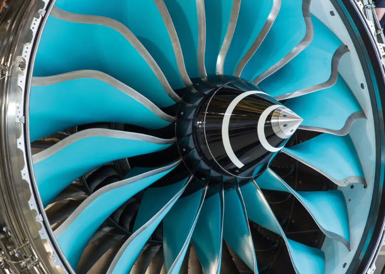
The modern high-bypass turbofan represents one of the most demanding optimization problems in structural engineering. The primary fan is the largest rotating assembly on an aircraft, swallowing tens of thousands of cubic feet of turbulent atmosphere per second. Every ounce of this rotating mass must be structurally sustained across broad thermal and rotational envelopes, and fully restrained by the containment system during catastrophic failure events such as a Fan Blade-Out (FBO).
For decades, titanium alloys (specifically Ti-6Al-4V) dominated the fan stage due to their high yield strength, ductile energy absorption, and fatigue limits. However, the physical bounds of metallic specific strength ($\sigma/\rho$) constrained high-bypass engine scaling. Over the last thirty years, Carbon Fiber Reinforced Polymers (CFRP) have systematically reshaped this trade space by altering fundamental centrifugal mechanics, structural dynamics, and containment physics.
Why Composites in the Fan Stage
Specific Strength, Modulus, and Density
Standard aerospace-grade titanium alloy Ti-6Al-4V exhibits a density of approximately $\rho = 4430\text{ kg/m}^3$ ($0.16\text{ lbm/in}^3$) with an ultimate tensile strength of $\approx 950-1050\text{ MPa}$. In contrast, a modern toughened intermediate-modulus epoxy CFRP laminate typically has a density of $\rho = 1550 – 1600\text{ kg/m}^3$—roughly 35% that of titanium.
While isotropic metals present uniform properties in all directions, unidirectional CFRP plies provide fiber-direction tensile moduli exceeding $160\text{ GPa}$ and tensile strengths exceeding $2500\text{ MPa}$. When tailored into a balanced multi-directional layup, the resulting structural component delivers superior specific stiffness ($E/\rho$) and specific strength ($\sigma/\rho$) compared to forged titanium.
The Cascading Centrifugal Mechanics
Centrifugal acceleration generates the primary static loading state within a rotating fan blade. Consider a differential mass element $dm$ located at radial distance $r$, rotating at angular velocity $\omega$. The centrifugal force $dF_c$ acting on the element is:
Integrating from a given radius $r$ to the tip radius $R_{\text{tip}}$ yields the total centrifugal tensile stress $\sigma_c(r)$ across cross-sectional area $A(r)$:
Notice that density $\rho$ directly scales the cross-sectional stress throughout the blade profile. Reducing $\rho$ by 65% fundamentally alters the downstream structural architecture through a multi-tiered compounding effect:
- Blade Root Sizing: Lower total mass directly decreases the root centrifugal pull force, reducing mechanical dovetail/pin attachment dimensions.
- Disk Rim Optimization: The fan disk sizing is dominated by rim hoop stress driven by blade pull. Lower blade mass permits a significantly lighter disk web and bore.
- FBO Energy Reduction: In a fan blade-out event, kinetic energy $E_k = \frac{1}{2}I\omega^2 + \frac{1}{2}mv^2$ scales linearly with blade mass $m$. A lighter blade dramatically reduces the impact kinetic energy that must be absorbed by the containment casing.
- Mount and Pylon Loads: Reduced rotating unbalance mass minimizes the dynamic transient and windmilling loads transmitted through engine mounts, pylon structures, and wing boxes after an FBO event.
- Bypass Ratio Expansion: The saved structural mass budget can be directly reinvested into expanding the fan tip diameter $D_{\text{fan}}$, raising the bypass ratio ($\text{BPR} > 10-12$) and boosting propulsive efficiency ($\eta_p$).
Anisotropy as an Aeroelastic Tuning Variable
An isotropic metallic blade limits the designer to geometric manipulations (taper, sweep, chord thickness) to adjust structural frequencies. In contrast, laminated CFRP blades offer a directionally tailored stiffness tensor $\mathbf{Q}_{ij}$. By adjusting ply orientation angles $\theta_k$, structural dynamicists can purposefully configure the blade’s constitutive behavior:
This anisotropic tailoring capability provides explicit control over key dynamic behaviors:
- Engine Order ($EO$) Avoidance: Modal frequencies (First Flap $1F$, First Torsion $1T$, Edgewise $1E$) can be tuned away from engine speed harmonics ($1X, 2X, 3X$) on the Campbell diagram to prevent sustained resonant fatigue.
- Bend-Twist Coupling ($\alpha_{\text{flex-tors}}$): Off-axis ply layups generate elastic coupling between bending deformations and torsional rotation. As aerodynamic loading or centrifugal untwist occurs, blade pitch dynamically adjusts, widening flutter margins across sub-sonic and trans-sonic flight regimes.
Production Engines Overview
The Impact Problem & Mitigation Mechanisms
Unlike internal turbofan components, the fan stage operates directly exposed to foreign object debris (FOD), ice shed, hail, and high-velocity bird strikes (regulated under FAR/CS 33.76). Pure polymer matrix composites exhibit inherent structural vulnerabilities under extreme impact loads:
- Low Interlaminar Shear Strength (ILSS): Matrix-dominated out-of-plane strength allows high-velocity transverse impacts to induce internal shear failure and extensive delamination between plies.
- Barely Visible Impact Damage (BVID): An impact can create catastrophic internal delamination and sub-surface matrix cracking without displaying clear surface ruptures, leading to severe Compression-After-Impact (CAI) strength knockdowns (often 40% to 60%).
- Brittle Fracture Mechanics: Unlike metallic alloys that absorb kinetic energy through plastic deformation ($\int \sigma \, d\epsilon$), composites absorb energy via brittle matrix cracking, ply delamination, and fiber breakage.
The Hybrid Mitigation Architecture: To satisfy airworthiness requirements, every production composite fan blade utilizes a bonded metallic leading edge (titanium or high-strength steel alloy). The metallic sheath performs three primary mechanical functions:
- It diffuses localized impact energy over a broader area of the underlying composite substrate.
- It offers high resistance to rain and sand erosion.
- It absorbs impact kinetic energy via plastic yield deformation before shear stresses transfer into the composite core.
Bond-Line Design and Load Transfer at the Metallic Leading Edge
The metallic sheath introduces its own structural problem: how to transfer load between a ductile, isotropic metal and a stiff, anisotropic laminate across a joint that must survive both discrete impact events and $10^7$ cycles of combined centrifugal and resonant loading. The retention strategy is a hybrid of adhesive bonding and geometric capture, with the balance varying by manufacturer.
Joint Architecture
The titanium (or Ti-alloy) sheath is a U-shaped wrap that captures the composite airfoil’s leading edge, with tapered wings extending aft along both the pressure and suction surfaces. Primary retention is adhesive—typically a toughened film adhesive with a scrim carrier for bond-line thickness control, either co-bonded with the laminate or secondary-bonded to a pre-cured airfoil. Fit tolerances are held tightly because bond-line thickness variation is a larger driver of joint strength scatter than the adhesive shear allowable itself.
The mechanical contribution comes from geometry rather than fasteners. The U-wrap provides mechanical capture against radial and chordwise pull-off, and the sheath is trapped at the root by the dovetail retention and platform. The adhesive therefore carries shear during normal operation, while the wrap geometry preserves the load path if the adhesive is locally disbonded. No fasteners are used—holes in a highly loaded rotating composite are unacceptable.
Wing Taper and Peel Stress
The taper on the sheath wings is the critical detail. Peak shear stress in a bonded joint scales with the adherend stiffness mismatch and the abruptness of the termination. The sheath is accordingly chamfered to a knife edge (often on the order of $0.1 – 0.3\text{ mm}$) to bleed load in gradually and maintain a smooth aerodynamic surface. An abrupt termination would create a peel stress concentration at precisely the location where a disbond would propagate aft.
Differential Thermal Loads
Titanium has a coefficient of thermal expansion of roughly $8.6\text{ ppm/}^\circ\text{C}$, while a carbon/epoxy laminate is near zero to slightly negative in the fiber direction and substantially higher transverse. The mismatch is real but manageable for three reasons:
- The fan operates over a modest temperature range compared with hot-section components (approximately $-55^\circ\text{C}$ to $+80^\circ\text{C}$ in service).
- The bond line is thin and the adhesive relatively compliant, accommodating differential strain in shear.
- Residual stress from cure cooldown is a known, characterizable pre-load rather than an unknown.
It manifests primarily as a fatigue-life debit on the bond line, accounted for within the design allowables.
What the Sheath Does and Does Not Do Under Impact
The sheath does not prevent delamination. It changes the failure mode and the energy partition.
What it does:
- Prevents fiber cutting and transverse penetration at the leading edge—the failure mode that would liberate a blade section.
- Distributes contact load over a much larger area and longer duration, reducing peak contact pressure by roughly an order of magnitude.
- Absorbs energy through plastic deformation; titanium’s ductility means the sheath dents and yields as a genuine energy sink.
What it does not do: the impulse still transmits into the laminate as a through-thickness stress wave and bending response, and interlaminar tension and shear still exceed matrix allowables locally. Sublaminate delamination near the impact site and at ply-drop locations is expected on bird-strike test articles, not anomalous. Certification is built around this reality—damage tolerance requires demonstrating that the blade retains structural capability with the damage present, and that the damage does not grow to critical size under subsequent cyclic loading.
Visibility and Inspection Strategy
Sheath deformation is a reliable visual flag for a significant strike, which is useful for a borescope-level inspection decision. But the correlation is not tight enough to rely upon: internal delamination can exist with only modest visible sheath dishing. The industry accordingly treats leading-edge deformation as a trigger for NDI (ultrasonic C-scan, thermography), not as a substitute for it. The damage-tolerance philosophy assumes undetected damage up to the BVID threshold is present, so the design must be adequate whether or not the sheath renders the event visible.
The harder qualification problem. The sheath-to-laminate bond must survive on the order of $10^7$ cycles of resonant blade vibration and centrifugal loading over the life of the part, with the thermal pre-load riding on top. Impact is a discrete event that can be tested to. Bond-line fatigue under combined loading is a statistical problem, and it is where the majority of the qualification effort actually goes.
Fatigue and Vibration Mechanics
Fiber-Dominated High-Cycle Fatigue (HCF)
Under axial load states dominated by fiber orientation, unidirectional CFRP exhibits outstanding High-Cycle Fatigue (HCF) behavior. The characteristic $S\text{-}N$ curve is significantly flatter than that of structural metals. The fatigue limit for fiber-dominated CFRP can reach $60\%\text{–}70\%$ of its static ultimate tensile strength, compared to approximately $40\%\text{–}50\%$ for Ti-6Al-4V.
Traditional metal fatigue damage follows single-dominant crack propagation governed by Paris’ Law:
Conversely, composites accumulate fatigue damage through distributed micro-mechanisms: matrix micro-cracking, transverse ply cracking, interfacial debonding, and localized delamination growth. Instead of a discrete crack length $a$, fatigue degradation manifests as a progressive reduction in overall structural stiffness $E(N)$.
Material Damping and Resonant Response
Aerodynamic excitation (inlet distortion, crosswinds, and stator wakes) drives steady-state vibration in the fan assembly. The dynamic response amplitude at resonance is inversely proportional to total system damping $\eta_{\text{total}}$:
The inherent material loss factor ($\eta$) of CFRP ($\eta \approx 0.005 – 0.015$) is roughly an order of magnitude higher than that of titanium ($\eta \approx 0.0005 – 0.002$). This elevated viscoelastic dissipation helps suppress resonant vibration peaks across high-frequency engine orders.
Fan Cases and Soft-Wall Containment Physics
Containment cases traditionally relied on heavy “hard-wall” metallic rings (forged steel or thick titanium) designed to resist penetration through shear punch and plastic deformation. Modern engines utilize “soft-wall” composite fan cases manufactured from braided or 3D-woven carbon/epoxy or Kevlar wrap structures.
Soft-wall containment operates on distributed energy dissipation mechanics:
Upon blade impact, the energy is absorbed as the composite casing undergoes large membrane deflections, extensive interlaminar delamination, fiber tensile fracture, and dry friction between expanding debris layers. This distributed energy absorption allows for drastic weight reductions in large-diameter engine nacelles.
Comparative Structural Trade Analysis
| Parameter / Feature | Titanium Alloy (Ti-6Al-4V) | Advanced Composite (CFRP) |
|---|---|---|
| Density ($\rho$) | $4430\text{ kg/m}^3$ (Base Reference) | $1550 – 1600\text{ kg/m}^3$ (~65% lighter) |
| Specific Modulus ($E/\rho$) | $\approx 25.7\text{ MPa}/(\text{kg/m}^3)$ | $\approx 70 – 90\text{ MPa}/(\text{kg/m}^3)$ (Fiber-dir.) |
| HCF Fatigue Limit | $40\%\text{–}50\%$ of Ultimate Strength | $60\%\text{–}70\%$ of Ultimate Strength (Fiber-dir.) |
| Aeroelastic Tuning | Restricted to geometric profiling | Tailorable directional laminate stiffness ($\mathbf{ABD}$ matrix) |
| Impact Mechanics | High ductility; plastic yield absorption | Brittle fracture; requires metallic leading-edge sheath |
| Leading-Edge Joint | Not applicable (monolithic) | Hybrid adhesive bond plus U-wrap geometric capture |
| Damage Tolerance | Single dominant crack (Paris Law) | Distributed stiffness degradation & BVID delamination |
| Thermal Limit | $> 400^\circ\text{C}$ ($750^\circ\text{F}$) | $\approx 175^\circ\text{C} – 200^\circ\text{C}$ ($350^\circ\text{F} – 400^\circ\text{F}$) |
Conclusion
The successful integration of composite materials into turbofan engine fan stages represents a triumph of system-level structural synthesis. A pure polymer matrix composite is fundamentally ill-suited for the harsh impact environment of an engine inlet. However, by combining high-modulus, low-density anisotropic carbon laminates with ductile metallic leading edges, aerospace engineers transformed a material vulnerability into a dominant structural advantage.
The metallic sheath does not eliminate the composite’s interlaminar weakness; it relocates the design problem into a bonded joint whose behavior can be characterized, tested, and certified. Through 30 years and over 300 million flight hours, composite fan systems have demonstrated that light, highly tailored structural components not only withstand complex centrifugal, dynamic, and impact loads, but also enable the wide-diameter, high-bypass ratio engines that define modern efficient aviation.
References & Further Reading
- Composites Today, “Rolls Royce Tests Composite Fan Systems for New Engine Designs,” September 2014. Link
- GE Aerospace, “Thirty Years and 300 Million Flight Hours Later, GE Aerospace’s Carbon Fiber Composites Are Ready for the GE9X Engine.”
- GE Aerospace, “GE’s Composite Fan Blade Revolution Turns 20 Years Old.”
- Rolls-Royce, UltraFan Technology Demonstrator Program Specifications and Updates, rolls-royce.com.
- CompositesWorld, “Rolls-Royce starts manufacture of world’s largest fan blades for UltraFan demonstrator.”
- Federal Aviation Administration, FAR 33.76 / CS-E 800 Airworthiness Standards: Bird Ingestion.
- L. J. Hart-Smith, “Adhesive-Bonded Double-Lap Joints,” NASA CR-112235, Douglas Aircraft Company, 1973.
- MIL-HDBK-17 / CMH-17, Composite Materials Handbook, Volume 3: Polymer Matrix Composites Materials Usage, Design, and Analysis.
📌 Turbofan Engine Knowledge Hub
Explore additional articles on turbofan engine acoustics, vibration, structural dynamics, fatigue, flight incidents, and aircraft noise measurements: Turbofan Engine Sound, Vibration & Structural Dynamics .
Looking for a deep dive on this topic? Explore our comprehensive guide and resource collection on the Residual Stress & Structural Integrity Hub.