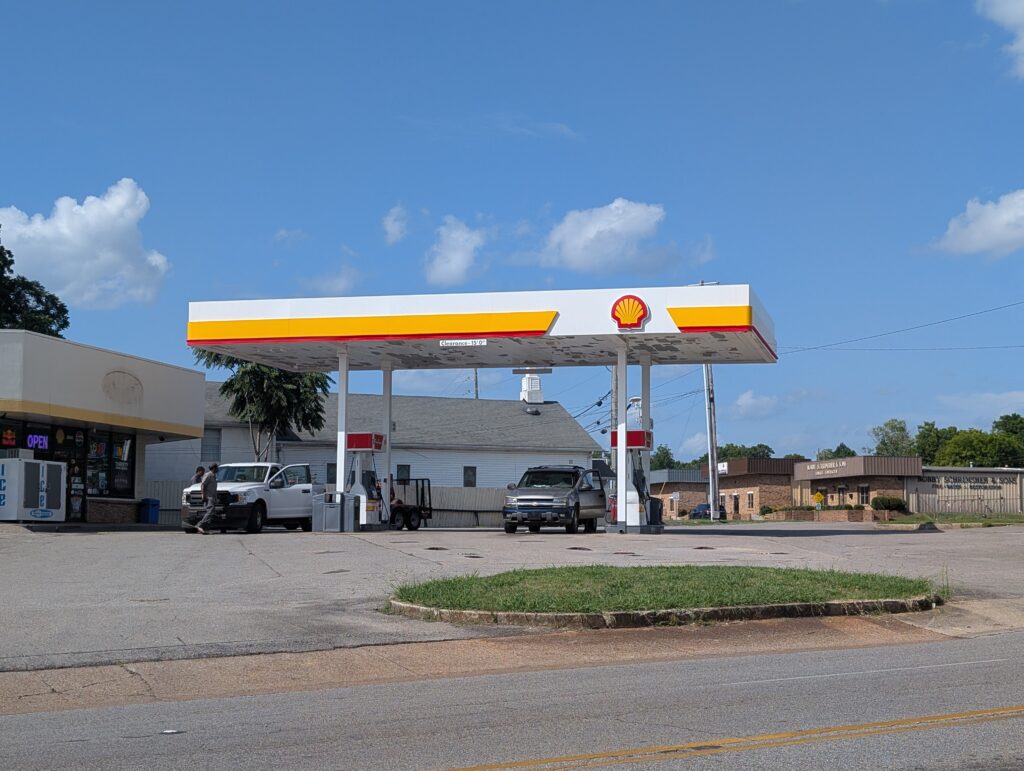
A Shell station on a Huntsville, Alabama arterial. Four slender columns, a flat deck roughly 60 feet by 30 feet, fifteen feet of clearance, and a fascia band carrying the brand colors. It is one of the most repeated structural forms in North America, and one of the least examined.
What drew my attention was the soffit. The underside of the deck shows extensive mottled patching — coating loss across a large fraction of the visible area, concentrated toward the perimeter. That is a durability observation I can make from the photograph. Everything that follows about the structural behavior is a discussion of the canopy as a structural class, not a diagnosis of this particular one.
The Structural System
A fuel canopy is an inverted pendulum problem. Nearly all the mass sits at the top of a set of cantilever columns, and the columns are the entire lateral system — there is no bracing, no shear wall, no diaphragm connection to an adjacent building. Whatever lateral resistance exists comes from moment connections at the column bases and from the deck acting as a rigid plate tying the column tops together.
The typical configuration is:
- Steel columns, commonly HSS or built-up sections, moment-fixed at the foundation through a base plate and anchor bolt group.
- A deck framed with steel joists or beams spanning between columns, with substantial cantilever overhangs beyond the column lines.
- Light-gauge metal or composite panels forming the soffit and fascia — architectural, not structural.
- Isolated spread footings or drilled piers, sized primarily to resist overturning rather than gravity.
The gravity load is modest. The self-weight of a canopy of this size is perhaps 15 to 25 psf. The columns are not working hard vertically. They are sized by lateral demand.
Wind: The Governing Case
Huntsville sits in the southern extension of the tornado corridor. The April 2011 outbreak produced multiple violent tornadoes across northern Alabama, and the region sees damaging straight-line wind and derecho events with some regularity. Wind governs the design of a structure like this, and not primarily through lateral drag.
Uplift is the controlling mechanism. ASCE 7 treats an open-sided monoslope or flat free roof as a distinct case, and the net pressure coefficients are large — a canopy is essentially an airfoil with flow on both surfaces. Wind moving across the deck generates suction above while the underside can be pressurized, particularly when the wind has a component along the long axis and flow is channeled beneath. The two effects add.
The consequence is that a canopy weighing 25 psf can face net uplift several times its own weight in a design wind event. Every element in the load path must be sized for a reversal that gravity does nothing to help resist:
- Deck panels to purlins
- Purlins to primary framing
- Framing to column tops
- Column base plates and anchor bolts in tension
- Foundation mass and soil resistance against pullout
The foundations of a canopy are frequently much larger than the modest gravity load would suggest, and that is why.
The cantilever overhang is the second concern. Corner and edge zones of a free roof carry the highest pressure coefficients, and on a canopy those zones are the unsupported overhangs. The combination of peak local pressure and maximum cantilever moment occurs at the same location. This is where observed failures often initiate.
Tornado loading is a different problem from straight-line wind. ASCE 7-22 introduced tornado load provisions for risk category III and IV structures, which a fuel canopy is not. But the physics are worth noting regardless: a tornado imposes rapid pressure change, strong vertical velocity components, and — critically for this discussion — a rotational flow field that loads the structure asymmetrically as the vortex translates past.
Torsional Behavior
The following is analytical reasoning about the canopy configuration in general. I have not measured this structure and am not claiming a deficiency in it.
A four-column canopy with a long, narrow plan has a torsional response worth thinking about carefully. Consider the plan geometry: columns roughly 60 feet apart along the long axis and 30 feet along the short. Torsional stiffness about a vertical axis comes from the columns’ lateral stiffness multiplied by the square of their distance from the center of rigidity. That distance is generous along the long axis and half as much along the short.
Write the torsional stiffness as
$$K_\theta = \sum_i k_i \, r_i^2$$
where $k_i$ is the lateral stiffness of column $i$ and $r_i$ its distance from the center of rigidity. With only four columns, the sum has four terms. There is no redundancy in it. If one base connection degrades — corroded anchor bolts, cracked grout, a footing that has settled — that column’s contribution drops and the center of rigidity shifts away from the center of mass. Eccentricity between the two produces torsion under any lateral load, including a purely translational one.
The relevant comparison is between the torsional and translational natural frequencies. When the ratio
$$\Omega = \frac{\omega_\theta}{\omega_y}$$
approaches unity, translational and torsional modes couple, and lateral excitation feeds energy into rotation. Structures with $\Omega$ near 1.0 are recognized as torsionally sensitive in seismic design practice. For a symmetric four-column canopy with equal member sizes, $\Omega$ is typically above 1.0 and the coupling is not severe. The concern arises when symmetry is lost — through unequal column stiffness, base connection deterioration, or differential foundation settlement.
Why this matters more for a canopy than for a building. A building has floor diaphragms, multiple frame lines, partitions, cladding, and a hundred sources of incidental stiffness and damping. A canopy has four columns and a plate. Its damping is low — a bare steel frame with no partitions and no cladding contributing friction might see 1 to 2% of critical. Torsional response under a translating tornado vortex, where the load direction sweeps through a large angle in seconds, is not a case the ordinary static design procedure directly addresses.
Seismic Demand
Northern Alabama is not a high-seismic region, but neither is it negligible. The area sits within the influence zone of the Eastern Tennessee Seismic Zone, one of the more active seismic features in the eastern United States by rate of small events, and the New Madrid Seismic Zone lies several hundred kilometers to the northwest. Ground motion from a large New Madrid event would arrive as long-period energy after considerable attenuation.
For a canopy, seismic demand is usually not the governing lateral case — the mass is small, and wind uplift is severe. But three characteristics deserve attention:
- The mass is concentrated at the top. A single-degree-of-freedom idealization is nearly exact, which makes the response easy to estimate but also means there is no higher-mode participation to distribute demand.
- The period is likely in the range where design spectra peak. A flexible steel cantilever system of this height and mass plausibly falls in the 0.5 to 1.0 second range, though this depends entirely on member sizes I do not have.
- Drift, not strength, is the practical concern. The columns are unlikely to yield. What fails first is the connection between the flexible frame and the rigid attachments — the fuel piping running up the column, the electrical conduit, the dispenser anchorage. Differential movement between a canopy column and a dispenser bolted to a slab is a fuel system integrity question, not just a structural one.
Snow and Ice
Huntsville’s ground snow load is low — the region sees occasional accumulation but nothing approaching northern design values. Snow does not govern a canopy in this climate.
Freezing rain is the more relevant winter hazard for the Tennessee Valley. Ice accretion adds distributed load and, more importantly, changes the aerodynamic profile of fascia and edge members. An iced canopy edge presents a modified section to wind, and combined ice-plus-wind load cases exist in ASCE 7 for precisely this reason.
The subtler winter effect is thermal. A long flat canopy with fixed column bases and no expansion joint will develop restraint stresses under temperature swing. A 60-foot steel span through a 60°F seasonal range moves roughly a quarter inch if free to expand. If the base connections resist that movement, the load goes into the columns and anchorage. Repeated seasonally, this is a fatigue mechanism — thousands of cycles over a service life, at modest stress amplitude, concentrated at the base plate weld.
The Observation From the Photograph
Returning to what is actually visible: the soffit coating has failed across much of the deck underside, with the loss appearing heaviest toward the perimeter and the overhangs.
Soffit deterioration on a canopy is not cosmetic, and the reason is specific to the geometry. The underside of a fuel canopy is a semi-enclosed volume open on all sides. It sees:
- Fuel vapor and combustion products from vehicles idling beneath
- Wind-driven rain entering from any direction, with no drainage path off the soffit face
- Road salt aerosol in winter, tracked in and thrown up by traffic
- Condensation, since the deck underside is a cold surface beneath a sun-heated deck
Once the coating is breached, water reaches the framing behind it. The structural members most exposed are the perimeter and overhang framing — which, as noted above, is also where wind pressure coefficients peak and cantilever moment is maximum. Section loss and peak demand coincide in the same members.
Whether that has occurred here is not determinable from a photograph taken across a street. What the photograph establishes is that the protective system has degraded enough to warrant looking behind it.
What Would Actually Answer the Question
The interesting thing about a canopy from a vibration standpoint is that its dynamic properties are easy to measure. A structure with a single dominant mass and low damping gives up its natural frequencies readily:
- Ambient vibration measurement. A triaxial accelerometer on the deck, wind excitation alone, and a Welch-averaged PSD would resolve the first translational modes and, with sensors at two corners, the torsional mode. This is the same method that recovered the Eiffel Tower’s fundamental mode to within 1% from a smartphone at the summit — a fuel canopy is a far easier target.
- Two-point measurement for torsion. Accelerometers at diagonally opposite corners, with the difference signal isolating rotation and the sum isolating translation. The frequency ratio $\Omega$ falls straight out of the two spectra.
- Base connection inspection. The single highest-value physical check. Anchor bolt condition, grout integrity, and base plate corrosion determine whether the assumed fixity actually exists.
- Coating and section loss survey. Ultrasonic thickness measurement on perimeter and overhang framing where the soffit has failed.
Summary
The fuel canopy is a structure designed almost entirely for a load case it may never experience. Its columns are not sized by the weight they carry but by the uplift they must resist and the drift they must limit. It has four columns and no redundancy in its lateral or torsional system. Its damping is low. Its most heavily loaded members sit at the overhang perimeter, which is also where the protective coating fails first.
None of that makes any particular canopy unsafe. It makes the class of structure one where the margin depends on details — base fixity, anchorage, coating condition — that are invisible from the road and easy to defer.
The one thing I can say about the canopy in the photograph is that its soffit has deteriorated substantially. What that means structurally requires someone to get up there and look.
References and Further Reading
- ASCE/SEI 7-22, Minimum Design Loads and Associated Criteria for Buildings and Other Structures — Chapter 27 and 29 for open buildings and free roofs, Chapter 32 for tornado loads, Chapter 10 for ice.
- AISC Steel Construction Manual — base plate and anchor rod design.
- ACI 318, Chapter 17 — anchorage to concrete.
- USGS National Seismic Hazard Model — for site-specific ground motion parameters.
Related free ebooks on modal testing, ambient vibration measurement, and shock and vibration response spectra: https://blog.vibrationdata.com/2025/11/27/toms-ebooks/
📌 Related Earthquake Engineering Knowledge Hub
This article is featured in our main Earthquake Engineering & Structural Dynamics Hub . Visit the hub to explore related articles on shock response spectra, time history analysis, seismic equipment qualification, and structural case studies.