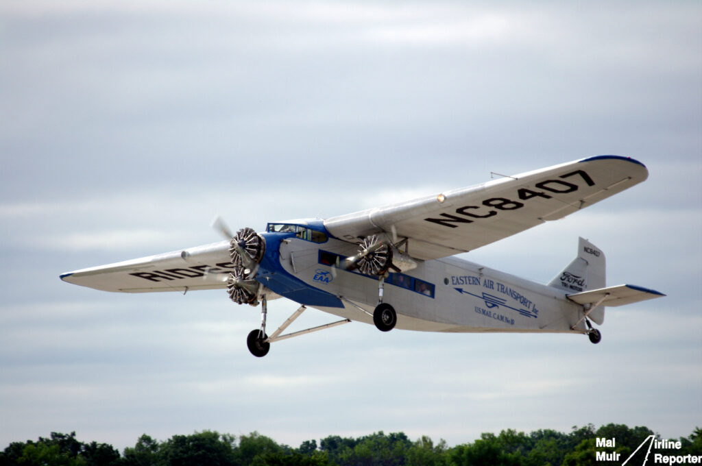
The “Tin Goose” convinced America that flying was safe. Nobody said anything about comfortable — a case study in excitation, transmission, and radiation.
The Tin Goose
The Ford Trimotor first flew on June 11, 1926, and 199 were built before production ended in 1933. It was the aircraft that convinced the American public that commercial air travel was safe and practical, flying for Transcontinental Air Transport (a TWA predecessor), Pan American, and roughly a hundred other airlines worldwide. Structurally it was a triumph: corrugated Alclad duralumin skin (a construction concept pioneered by Junkers — who successfully sued Ford over the resemblance), all-metal control surfaces, and a ruggedness that kept examples flying scenic tours nearly a century later.
Dynamically, it was one of the harshest passenger environments in transport-aviation history. The Trimotor did not have a vibration failure problem. It had a vibration comfort problem of legendary proportions — and it makes a wonderful case study in excitation sources, transmission paths, and radiating surfaces.
The Excitation Sources
The definitive 5-AT model carried three Pratt & Whitney R-1340 Wasp engines: 9-cylinder, air-cooled radials of 420 hp each, direct-drive (no reduction gearbox), turning 9-foot two-blade fixed-pitch propellers. Typical operating speeds were about 2,300 RPM for takeoff and 1,800 RPM in cruise. That gives a well-populated source spectrum, per engine:
| Source | Order | 1,800 RPM | 2,300 RPM |
|---|---|---|---|
| Shaft rate (imbalance, prop track error) | 1P | 30 Hz | 38.3 Hz |
| Propeller blade-passing | 2P | 60 Hz | 76.7 Hz |
| Engine firing (9 cyl, 4-stroke) | 4.5N | 135 Hz | 172.5 Hz |
| Firing harmonics | 9N, 13.5N… | 270, 405 Hz… | 345, 517.5 Hz… |
A two-blade fixed-pitch prop is also the worst case for once- and twice-per-rev excitation: any aerodynamic asymmetry, track error, or mass imbalance drives strong 1P and 2P forcing, and modern flight-test data on two-blade props consistently shows 2P as the dominant cabin vibration line.
The propeller tips deserve special mention. A 9-ft prop at 2,300 RPM has a rotational tip speed of about 1,080 ft/s; adding the forward-flight component, the helical tip Mach number approaches unity on takeoff. Peter Garrison, flying a restored Trimotor for Flying magazine, described a takeoff sound of six near-sonic propeller tips that came in through the bones, undiminished by covering his ears — intense, broadband-rich noise radiated directly against an unsealed, uninsulated fuselage sitting in the propellers’ near field.
The Transmission Path: No Isolation, Anywhere
The Wasps were bolted to the airframe through rigid steel-tube mounts — elastomeric engine isolators were only beginning to appear in this era. Every firing pulse and every 1P/2P prop load went straight into the structure. The engines were uncowled, so there was no nacelle to absorb or redirect anything.
Two period details tell you everything about the vibration levels:
- Engine gauges were mounted outside, on the engines and nacelle struts, read by the pilot through the windshield. Panel-mounted instruments of the day could not survive — or be read through — the cockpit vibration.
- Control cables ran along the exterior of the fuselage, and the control surfaces themselves were corrugated metal — every surface a potential rattle and radiator.
The Radiating Surface: A Corrugated Sounding Board
The corrugated skin that made the Trimotor stiff and rugged also made it an efficient acoustic radiator. Corrugation raises the panel bending stiffness dramatically in one direction, altering coincidence behavior and coupling structure-borne vibration efficiently into the cabin. With no interior trim, no insulation blankets, and no double-wall construction, the passenger sat inside a reverberant aluminum drum, in the plane of two propellers, a few feet from three unmuffled radial exhausts.
Period remedy — cabin noise levels are commonly cited in the 110–120 dB range. Airlines handed out cotton wool; early stewardesses used speaking tubes and megaphones; career Trimotor pilots commonly suffered permanent hearing loss. Passengers reported that after a transcontinental day aboard the Ford, the ringing lasted through the night.
Three Engines, No Synchrophaser: Life Inside a Beat Pattern
Here is my favorite part. The three direct-drive engines had no synchronization system. Garrison reports the pilots continually chasing prop sync by ear — and that even when momentarily matched, the three props would not stay that way for long.
Three engines at slightly different speeds produce three simultaneous beat pairs. If the engines are at, say, 1,790, 1,800, and 1,815 RPM, the 1P beat frequencies are:
Engines 2–3: (1815 − 1800)/60 = 0.25 Hz
Engines 1–3: (1815 − 1790)/60 ≈ 0.42 Hz
…and twice those values at the dominant 2P blade-passing line. The cabin sound and vibration would swell and fade in a slow, wandering triple-beat modulation — felt structurally as well as heard, since the beats exist in the forcing functions themselves, not just the acoustics.
Readers may recall my CRJ-900 descent audio analysis from June, where the two CF34 fans differed by about 50 RPM and produced a clean 0.83 Hz beat with ~99% modulation depth. The Trimotor passenger of 1929 lived inside the three-engine version of that phenomenon, at vastly higher levels, for two- and three-hour legs. Modern turboprops solve this with synchrophasers that lock relative blade phase; the Trimotor solved it with cotton wool.
Structure vs. Comfort: The Verdict
It is worth closing on the contrast. Despite this ferocious dynamic environment, the Trimotor’s airframe was sound. The corrugated skin and steel-tube structure absorbed decades of rough-field operations, and the type’s retirement was driven by aerodynamics and economics — the sleek, faster DC-2 and DC-3 — not by fatigue failures. The Trimotor is thus a clean historical example of the distinction between structural adequacy and dynamic environment: an airplane can be simultaneously overbuilt and unbearable.
Within a decade, the industry answered every one of the Trimotor’s dynamic sins: elastomeric engine mounts, NACA cowlings, geared engines with lower prop speeds and three-blade props, stressed-skin monocoque fuselages with trim and insulation, and eventually propeller synchronization. Cabin noise fell by tens of decibels between the Ford and the DC-3. The Tin Goose showed the world that flying was safe; the next generation had to show that it was tolerable.
For the underlying methods — beat frequencies, sound level metrics, sine vibration, and acoustic fatigue — see my free ebooks: blog.vibrationdata.com/toms-ebooks · vibrationdata.com
Sources
- Peter Garrison, “A Trip Back in Time with the Ford Trimotor,” Flying — flyingmag.com/trip-back-in-time-with-ford-trimotor/
- Smithsonian National Air and Space Museum, Ford 5-AT Tri-Motor — airandspace.si.edu/collection-objects/ford-5-at-tri-motor/nasm_A19740489000
- Wikipedia, Ford Trimotor — en.wikipedia.org/wiki/Ford_Trimotor