Introduction
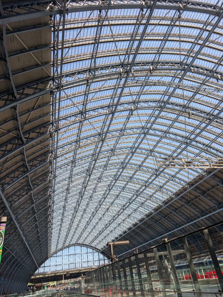
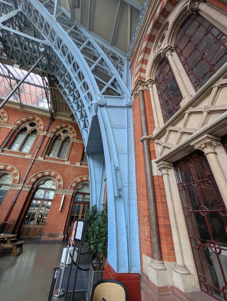
Some of the best structural engineering field trips are unplanned. While passing through St Pancras International station in London, I photographed three artifacts that together tell a 159-year story of structural engineering: the great Barlow train shed roof, a foundry plate cast in 1867, and a small wooden box at the base of an iron arch rib bearing the quiet notice, “Please do NOT touch. Monitoring work in progress.” The Victorians built the structure; their successors are instrumenting it.
The Barlow Train Shed
The St Pancras train shed was designed by William Henry Barlow, consulting engineer to the Midland Railway, with Rowland Mason Ordish, and completed in 1868. Its single wrought iron arch span of 245 feet 6 inches (about 74.8 m), rising roughly 100 feet above the platforms, made it the largest single-span roof in the world at its completion, a title it held for years. The span is crossed by lattice arch ribs spaced about 29 feet apart, each built up from riveted wrought iron.
The structural scheme contains an elegant trick that every arch designer will appreciate. An arch of this span produces an enormous horizontal thrust at its springings. Rather than resist that thrust with massive abutments, Barlow tied the arch feet together with iron ties running beneath the platform deck: the station floor itself is the tie of the arch. The arch ribs spring from below platform level, and the thrust is closed internally, leaving the perimeter walls to carry primarily gravity load. As a bonus, the undercroft beneath the tied floor was dimensioned around the storage of beer barrels from Burton-upon-Trent, one of the Midland Railway’s prize cargoes; the column grid was literally set by barrel geometry. Form followed freight.
The slightly pointed profile of the arch is not just Gothic sympathy with George Gilbert Scott’s Midland Grand Hotel facade next door. A pointed arch draws the funicular of the dominant loading closer to the rib centerline, reducing bending in the rib, and it stiffens the crown against the asymmetric load cases (wind, and in the original design, drifting smoke ventilation openings) that govern arch bending moments.
The Butterley Company, 1867
At the base of one rib, a proud oval plate reads “Manufactured by the Butterley Company, 1867, Derbyshire.” Butterley was one of the great Midlands ironworks, and the St Pancras roof was among its signature commissions. The same firm, remarkably, was still winning landmark structural work into the twenty-first century: the Falkirk Wheel boat lift in Scotland (2002) was a Butterley project before the company’s final closure in 2009. A 142-year span between those two jobs is a corporate fatigue life worth honoring.
The date matters for materials engineering. 1867 is squarely in the wrought iron era, after cast iron had been discredited for major spans in tension and bending (the Dee Bridge disaster of 1847 taught that lesson) and before Bessemer and open-hearth steel displaced wrought iron in the 1880s and 1890s. Wrought iron is a low-carbon ferrous material worked with slag inclusions drawn into stringers, which makes it anisotropic, tough and ductile along the grain, with good corrosion resistance from the slag films, but with fatigue-relevant discontinuities built into the microstructure. Typical properties: elastic modulus around 185 to 195 GPa, yield strength on the order of 200 to 220 MPa, ultimate strength around 280 to 350 MPa. Riveted wrought iron construction is generally assessed today with conservative fatigue detail categories, and the punched rivet holes, not the parent metal, are usually the fatigue-critical features.
The Loading Environment: Natural and Man-Made
A structure that has stood since 1868 has seen nearly every load case the textbooks catalog, and a few they do not. The natural sources first:
- Snow. For a large arch roof, the governing case is usually not uniform snow but drifted, asymmetric snow, which pushes the load funicular away from the rib centerline and generates the bending moments that size the lattice. The slightly pointed profile helps here, stiffening the crown region where asymmetric load bites hardest.
- Wind. The curved roof sees pressure on the windward flank and suction over the crown and leeward flank, with gust energy concentrated below a few Hz, quasi-static for a structure of this stiffness but a fatigue actor over 159 years of storms.
- Thermal cycling. With a coefficient of expansion around \( 12 \times 10^{-6} /^{\circ}C \), a 30 degree C seasonal swing works the 74.8 m span through
of free expansion demand, cycled annually for 159 years, with smaller diurnal cycles superimposed. In a tied arch, restrained thermal expansion converts directly into rib and tie force fluctuation.
- Ground movement. The station sits on London clay, a shrink-swell soil sensitive to groundwater changes, seasonal moisture, and adjacent excavation. Differential settlement between rib feet is precisely the slow, secular effect that distinguishes itself from reversible thermal motion only in long-term monitoring data.
- Seismicity. UK seismic hazard is low but not zero; London has felt regional events such as the 1931 Dogger Bank earthquake. For this structure it is a minor entry in the load ledger, but a nonzero one.
The man-made sources are arguably the more interesting list:
- Train-induced vibration. The tenants have changed from Midland Railway steam locomotives to 400 m Eurostar trainsets, with ground-borne vibration typically in the 5 to 100 Hz range transmitted through the tied floor, the very member that closes the arch thrust. Beneath and beside the station, six London Underground lines and the Thameslink route add their own broadband rumble around the foundations.
- Footfall and crowd loading. The concourse and undercroft floors see pedestrian excitation near 2 Hz and its harmonics, a serviceability rather than strength issue, but a real one for the inserted modern floors.
- Construction vibration. The King’s Cross and St Pancras district has been under more or less continuous heavy construction for two decades: the HS1 works themselves, deep basements, piling, and the Canal Tunnels brought into service in 2016. Piling and tunneling transients are exactly what the BS 7385-2 peak particle velocity criteria exist to police around heritage masonry.
- Blast. The shed was hit by bombs in both World Wars, including a deadly 1917 Zeppelin-era air raid, and was patched and returned to service each time. Genuine high-rate blast loading is a load case few structures experience and survive; the wrought iron’s ductility, and the redundancy of 24 ribs sharing the roof, deserve much of the credit. Readers of my Hopkinson-Cranz post on the New Glenn pad explosion will recognize that surviving blast is as much about ductile energy absorption as about strength.
| Source | Character | Typical frequency content |
|---|---|---|
| Dead load | Static | — |
| Drifted snow | Quasi-static, asymmetric | — |
| Wind gusts | Quasi-static plus dynamic | < 2 Hz |
| Thermal | Cyclic strain demand | Diurnal and annual |
| Footfall / crowds | Dynamic, serviceability | 1.5 – 2.5 Hz and harmonics |
| Trains (surface and Underground) | Ground-borne dynamic | 5 – 100+ Hz |
| Construction (piling, tunneling) | Transient, PPV-limited | Broadband transients |
| Ground movement / settlement | Secular trend | Months to decades |
| Blast (WWI, WWII) | High-rate transient | Impulsive |
The Monitoring Box
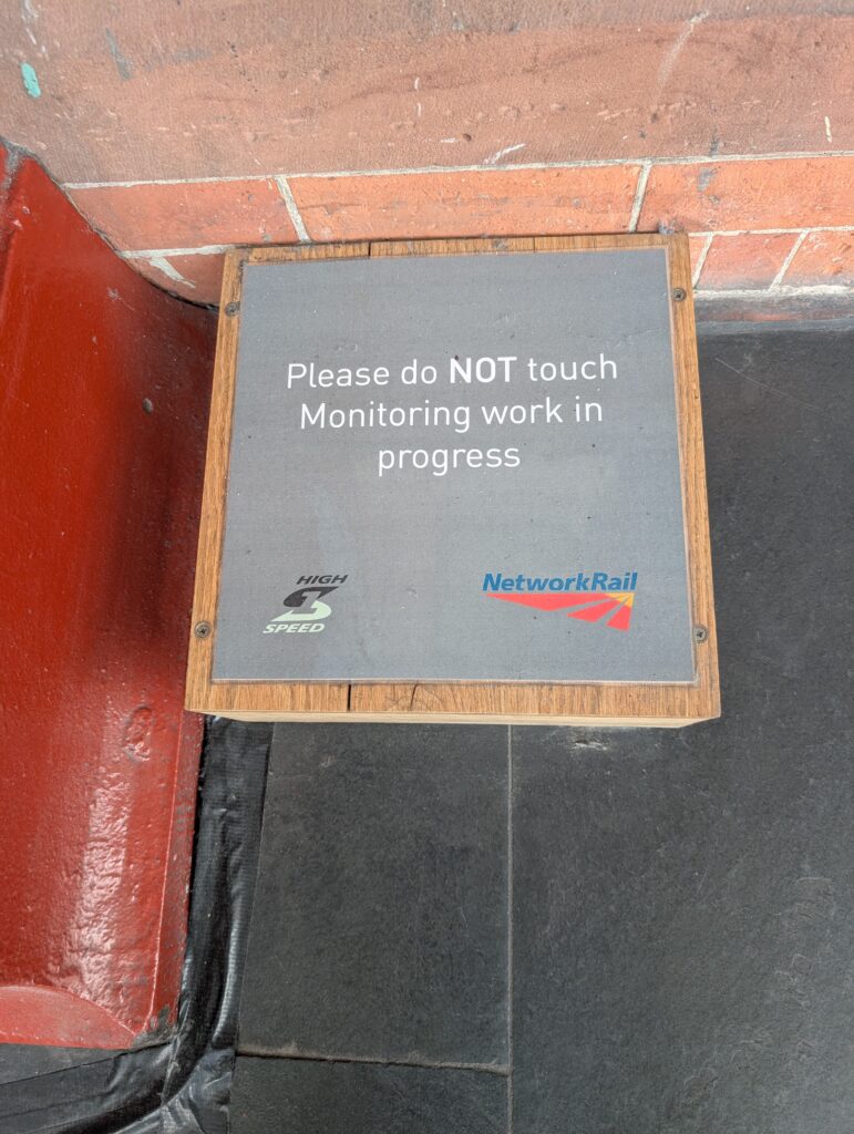
Figure 3: Network Rail High Speed monitoring enclosure
The wooden box at the rib base, labeled by Network Rail (High Speed), the infrastructure manager for the HS1 route and St Pancras, is a protective cover over a structural health monitoring installation. Enclosures of this kind at the base of a historic iron arch typically house one or more of the following:
- Crack or joint displacement gauges, vibrating wire or LVDT transducers spanning a monitored crack or interface, logging opening and closing to fractions of a millimeter,
- Tiltmeters, tracking rotation of the rib base or adjacent masonry,
- Geophones or accelerometers, measuring train-induced and construction-induced vibration against criteria such as BS 7385-2 for building damage and BS 6472 for human response.
Why monitor a structure that has stood since 1868? Because the demands on it keep changing, as the load ledger above makes clear. The 2001 to 2007 reconstruction for the Channel Tunnel Rail Link converted the shed into the Eurostar terminal, extended the station, inserted new floors and openings into the undercroft, and put 400 m high-speed trainsets where steam locomotives once stood. Any of those changes redistributes load paths in a tied-arch system where the floor is a primary structural member, and the surrounding district has seen continuous deep construction. The monitoring task is one of signal separation: the 27 mm annual thermal breathing and the daily train-induced vibration are the benign, reversible signatures, roughly 160 slow thermal cycles superimposed on millions of train cycles. Long-term monitoring separates those from any secular trend that would signal foundation movement, tie distress, or masonry cracking. The measured trend, not the visual inspection alone, drives the intervention decision. This is exactly the modern philosophy: measure, establish the baseline signature, and let departures from the baseline raise the alarm.
There is a pleasing continuity here with the ad hoc measurements I have been collecting on my travels, such as the accelerometer and audio data from the London Eye capsule a few days ago. The difference is commitment: my smartphone rode the Eye for one revolution, while the little box at St Pancras sits in the corner logging around the clock, year after year, building the statistical baseline that makes anomaly detection possible.
Closing Thoughts
Barlow’s shed is a masterclass in load path clarity: arch for gravity, floor as tie, thrust closed internally, all of it legible from the concourse with a refreshing drink in hand. The Butterley plate reminds us that every structure is also a materials time capsule, and the monitoring box reminds us that stewardship of old structures is an instrumentation problem as much as an analysis problem. When you pass through a great station, look down at the rib bases as well as up at the roof. The most interesting engineering is sometimes in a plain wooden box.
My free ebooks on shock, vibration, and fatigue are available here: https://blog.vibrationdata.com/2025/11/27/toms-ebooks/
References
- Barlow, W.H., “Description of the St. Pancras Station and Roof, Midland Railway,” Minutes of the Proceedings of the Institution of Civil Engineers, Vol. 30, 1870.
- Historic England, St Pancras Station and Midland Grand Hotel, Grade I listing documentation.
- BS 7385-2, Evaluation and Measurement for Vibration in Buildings, Part 2: Guide to Damage Levels from Groundborne Vibration, British Standards Institution.
- BS 6472-1, Guide to Evaluation of Human Exposure to Vibration in Buildings, British Standards Institution.
- Sutherland, R.J.M. (ed.), Structural Iron 1750-1850, and Thorne, R. (ed.), Structural Iron and Steel 1850-1900, Studies in the History of Civil Engineering, Ashgate.
📌 Related Earthquake Engineering Knowledge Hub
This article is featured in our main Earthquake Engineering & Structural Dynamics Hub . Visit the hub to explore related articles on shock response spectra, time history analysis, seismic equipment qualification, and structural case studies.