Introduction
Uniaxial fatigue methods, whether stress-life, strain-life, or spectral, presume that a single stress or strain component tells the whole damage story. Real hardware disagrees. Shafts carry bending plus torsion, pressure vessel nozzles see biaxial membrane stress plus thermal bending, and vibrating structures respond in multiple modes whose stress fields combine with shifting orientation. When the loading is multiaxial, and especially when it is non-proportional, the familiar trick of collapsing the stress state into a von Mises equivalent quietly fails. The critical plane method is the modern answer: evaluate fatigue damage on candidate material planes individually, and let the plane with the maximum damage, the critical plane, govern the life prediction. The method has a decisive physical advantage over invariant-based approaches: it predicts not only the fatigue life but also the orientation of the crack.
Why Equivalent Stress Fails
Consider a shaft under fully reversed bending and fully reversed torsion of fixed amplitudes. Apply them in phase, and then again 90 degrees out of phase. The von Mises equivalent stress amplitude can be identical in both cases, yet the fatigue lives differ, sometimes by a factor of ten, with the out-of-phase case usually worse for ductile metals. Two physical effects are responsible:
- Rotating principal axes. Under proportional loading, the principal directions are fixed and one material plane accumulates all the damage. Under non-proportional loading, the principal axes rotate during the cycle, sweeping shear across many slip systems and activating more of the microstructure.
- Non-proportional cyclic hardening. The multidirectional slip produces additional hardening beyond the proportional cyclic curve, up to a factor of two in cyclic stress for austenitic stainless steels such as 304, which raises the stress response for a given strain path and accelerates damage.
A scalar invariant such as von Mises is blind to both effects, and, being sign-less, it cannot even distinguish tension from compression. The critical plane method addresses the problem at its physical root.
The Physical Basis: Where Cracks Are Born
Fatigue cracks in metals nucleate by cyclic slip. In Stage I, the microcrack grows along shear planes, driven by shear strain amplitude, with the normal stress on that plane acting as a modifier: tensile normal stress pries the crack faces apart, reduces friction and interlocking between the faces, and accelerates growth, while compressive normal stress does the opposite. In Stage II, the crack turns to grow perpendicular to the maximum principal stress. Materials differ in how much of their life is spent in each stage. Ductile metals at short lives are shear-dominated; higher-strength and more brittle materials, and long lives, tend toward tensile (normal stress) domination. Brown and Miller further distinguished Case A cracks, which grow along the surface, from Case B cracks, which drive into the depth; Case B is the more dangerous, and biaxial stress states that promote it (such as equibiaxial loading) are correspondingly more damaging than uniaxial data would suggest.
The critical plane method encodes this physics directly: the damage parameter on each plane combines the shear term that drives Stage I with a normal stress or strain term that modifies it.
The Method in Outline
- Obtain the stress and strain tensor histories at the point of interest, from strain gauges, elastic FEA with a notch correction, or elastic-plastic FEA.
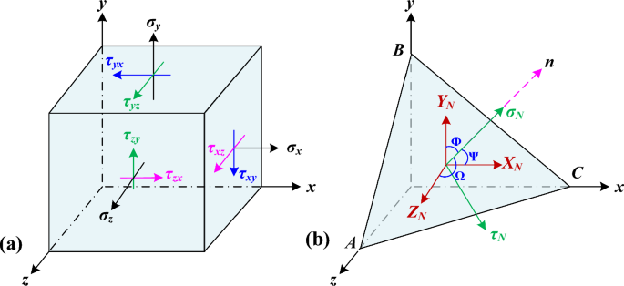
- Define a family of candidate planes through the point, parameterized by two angles \( (\theta, \phi) \), typically swept in 5 to 10 degree increments (10 degree increments give 648 planes over the hemisphere; symmetry reduces the count).
- On each plane, resolve the tensor histories into the normal stress \( \sigma_n(t) \), normal strain \( \varepsilon_n(t) \), shear stress \( \tau(t) \), and shear strain \( \gamma(t) \) acting on that plane.
- Cycle-count the resolved history on each plane and evaluate the chosen damage parameter, summing damage per Miner’s rule for variable amplitude loading.
- The plane with the maximum damage is the critical plane; its damage gives the life prediction and its orientation gives the expected crack plane.
Two implementation subtleties deserve mention. First, the shear stress on a plane is a two-dimensional vector that traces a closed path during a cycle; defining its “amplitude” for a non-proportional path is itself a research topic, with the longest chord, longest projection, minimum circumscribed circle, and maximum rectangular hull methods in common use. Second, cycle counting must be performed per plane on the resolved history, using rainflow on a suitable scalar channel or the Wang-Brown multiaxial counting method; counting on the raw global components and then resolving gives wrong answers for non-proportional paths.
The Principal Damage Parameters
Findley (1959), stress-based
\[ \left( \tau_a + k \, \sigma_{n,max} \right)_{max \; over \; planes} = f \]The earliest and still widely used critical plane criterion, appropriate for high cycle fatigue. The constant \( k \) expresses the material’s normal stress sensitivity and is calibrated from two fatigue limits, typically fully reversed bending and fully reversed torsion; \( k \) is commonly in the range 0.2 to 0.3 for ductile metals. Findley is the backbone of several code procedures, including the FKM guideline’s critical plane option and common gear and weld applications.
Brown-Miller (1973), strain-based
Brown and Miller proposed that the maximum shear strain amplitude and the normal strain excursion on the maximum shear plane jointly control damage. The Kandil-Brown-Miller working form, as implemented in commercial durability codes:
\[ \frac{\Delta\gamma_{max}}{2} + \frac{\Delta\varepsilon_n}{2} = 1.65 \frac{\sigma_f’}{E} (2N_f)^b + 1.75 \, \varepsilon_f’ (2N_f)^c \]with a Morrow-type mean stress correction applied to the elastic term. Note the pleasant economy: the right-hand side uses the same four strain-life constants \( \sigma_f’, b, \varepsilon_f’, c \) from ordinary uniaxial testing, rescaled by factors derived from the assumption of shear-dominated cracking. Brown-Miller is the default multiaxial algorithm for ductile metals in several commercial fatigue solvers.
Fatemi-Socie (1988), strain-based with stress modifier
\[ \frac{\Delta\gamma_{max}}{2} \left( 1 + k \frac{\sigma_{n,max}}{\sigma_y} \right) = \frac{\tau_f’}{G} (2N_f)^{b_0} + \gamma_f’ (2N_f)^{c_0} \]The Fatemi-Socie parameter multiplies the shear strain amplitude by a normal stress factor, capturing the crack-face-opening physics described above, and it inherently accounts for mean stress and for non-proportional hardening, since the extra hardening raises \( \sigma_{n,max} \). The right-hand side uses torsional fatigue constants; when these are unavailable, they can be estimated from the uniaxial constants via von Mises relations. Fatemi-Socie is the parameter of choice for shear-dominated (Mode II initiating) materials such as many wrought steels and titanium alloys.
Smith-Watson-Topper, critical plane form
\[ \sigma_{n,max} \, \frac{\Delta\varepsilon_1}{2} = \frac{(\sigma_f’)^2}{E} (2N_f)^{2b} + \sigma_f’ \varepsilon_f’ (2N_f)^{b+c} \]Here the candidate planes are searched for the maximum product of normal stress and principal strain amplitude. SWT is the appropriate choice for tensile-dominated (Mode I initiating) materials, including cast irons, some cast aluminums, and high-strength steels at long lives. It predicts zero damage for fully compressive cycles, consistent with crack closure.
Dang Van (1973), mesoscopic scale
\[ \tau(t) + a_{DV} \, \sigma_h(t) \le b_{DV} \]The Dang Van criterion operates at the grain (mesoscopic) scale, combining the instantaneous microscopic shear stress with the hydrostatic stress, and is formulated as an infinite-life (endurance) criterion rather than a finite-life predictor. It is entrenched in the automotive and bearing industries for high cycle multiaxial screening.
Other notable formulations include Matake and McDiarmid (maximum shear plane with normal stress correction), Carpinteri-Spagnoli (weighted principal directions), Susmel-Lazzarin’s Modified Wöhler Curve Method, and Liu-Mahadevan. The field is crowded, but the practical guidance is stable: match the parameter to the material’s cracking mode, Fatemi-Socie or Brown-Miller for shear-dominated behavior, SWT for tensile-dominated behavior.
| Parameter | Basis | Plane searched | Best suited for |
|---|---|---|---|
| Findley | Stress | Max of τa + kσn,max | HCF, code applications, welds, gears |
| Brown-Miller (KBM) | Strain | Max shear strain plane | Ductile metals, general durability, LCF-HCF |
| Fatemi-Socie | Strain × stress | Max shear strain plane | Shear-dominated metals, non-proportional loading |
| SWT (critical plane) | Stress × strain | Max of σn,maxΔε1/2 | Tensile-dominated metals, cast alloys |
| Dang Van | Mesoscopic stress | Instantaneous shear + hydrostatic | HCF infinite-life screening |
A Compact Illustration
Take a smooth steel shaft under fully reversed bending stress amplitude \( \sigma_a = 200 \) MPa combined with fully reversed torsional stress amplitude \( \tau_a = 115 \) MPa, first in phase and then 90 degrees out of phase. The von Mises equivalent amplitude in the in-phase case is
\[ \sigma_{vm,a} = \sqrt{\sigma_a^2 + 3\tau_a^2} = \sqrt{200^2 + 3(115)^2} \approx 283 \;\text{MPa} \]For the out-of-phase case, the instantaneous von Mises value \( \sqrt{\sigma^2(t) + 3\tau^2(t)} \) with \( \sigma = 200\cos\omega t \) and \( \tau = 115\sin\omega t \) is nearly constant in time, about 199 to 200 MPa, so a naive equivalent stress analysis concludes the out-of-phase loading is much less damaging. Experiments on ductile steels show the opposite: the out-of-phase case is typically as damaging or more so, because the principal axes rotate continuously and non-proportional hardening raises the stress response. A critical plane search resolves the paradox. In the in-phase case, one plane sees the full combined shear excursion. In the out-of-phase case, no single instant maximizes both components, but the rotating stress state ensures that many planes each experience large shear cycles with significant tensile normal stress at the worst-case orientation, and the Fatemi-Socie or Findley parameter on the critical plane correctly ranks the out-of-phase loading as severe rather than benign. This simple case is the standard demonstration of why the critical plane method exists.
Critical Plane Methods in the Frequency Domain
For random vibration, the critical plane concept marries naturally with spectral fatigue methods. Given the cross-spectral density matrix of the stress components at a point, from a random vibration FEA solution, the PSD of the resolved normal and shear stresses on any candidate plane follows by a linear projection: if \( \sigma_n(t) = \mathbf{a}^T \mathbf{s}(t) \) for projection vector \( \mathbf{a} \) and stress component vector \( \mathbf{s} \), then
\[ G_{\sigma_n}(f) = \mathbf{a}^T \, \mathbf{G}_{ss}(f) \, \mathbf{a} \]One then applies a spectral fatigue estimator, Dirlik or a corrected variant, to the resolved PSD on each plane and searches for the critical plane in the frequency domain. This is the multiaxial extension of the spectral fatigue problem I addressed in my Meta-Dirlik work presented at Fatigue 2026: the per-plane resolved PSDs are often broadband even when the component PSDs are narrowband, so the broadband bias corrections matter, and the plane search multiplies the number of spectral evaluations by several hundred, which puts a premium on fast, closed-form estimators. Equivalent von Mises PSD methods (Segalman-Preumont) offer a cheaper alternative but inherit the sign-blindness and non-proportionality blindness of the invariant approach.
Practical Guidance
- Check proportionality first. If the loading is proportional (fixed principal directions), a uniaxial method on the maximum principal or signed von Mises stress is usually adequate, and the critical plane machinery adds cost without much accuracy.
- Match the parameter to the material’s cracking behavior; if unknown, run both a shear parameter (Fatemi-Socie) and a tensile parameter (SWT) and take the shorter life.
- Calibrate with at least one torsional fatigue curve where possible. Estimating shear constants from uniaxial data via von Mises relations is a common but appreciable approximation.
- Watch the plane search resolution. Coarse angular increments can miss the critical plane by enough to matter at steep S-N slopes; 10 degrees is a common compromise, refined locally around the maximum.
- For welds, note that dedicated methods (structural hot spot, notch stress, Findley-based approaches per the FKM guideline and IIW recommendations) are usually preferable to raw critical plane analysis at the weld toe.
Closing Thoughts
The critical plane method is the rare analysis framework that improved both the physics and the bookkeeping: it grounds the damage parameter in the observed mechanics of crack nucleation, and as a bonus it hands the analyst the predicted crack orientation, a falsifiable claim that invariant methods cannot make. The cost is computational, several hundred plane evaluations per location with per-plane cycle counting, but on modern hardware that cost is trivial next to the FEA solution that feeds it. A MATLAB implementation of the plane search with Findley, Fatemi-Socie, and SWT parameters, in both time and frequency domains, is planned as future work.
My free ebooks on fatigue, shock, and vibration are available here: https://blog.vibrationdata.com/2025/11/27/toms-ebooks/
References
- Socie, D.F., Marquis, G.B., Multiaxial Fatigue, SAE International, 2000.
- Findley, W.N., “A Theory for the Effect of Mean Stress on Fatigue of Metals Under Combined Torsion and Axial Load or Bending,” Journal of Engineering for Industry, Vol. 81, 1959.
- Brown, M.W., Miller, K.J., “A Theory for Fatigue Failure Under Multiaxial Stress-Strain Conditions,” Proceedings of the Institution of Mechanical Engineers, Vol. 187, 1973.
- Kandil, F.A., Brown, M.W., Miller, K.J., “Biaxial Low-Cycle Fatigue Failure of 316 Stainless Steel at Elevated Temperatures,” The Metals Society, London, 1982.
- Fatemi, A., Socie, D.F., “A Critical Plane Approach to Multiaxial Fatigue Damage Including Out-of-Phase Loading,” Fatigue & Fracture of Engineering Materials & Structures, Vol. 11, No. 3, 1988.
- Smith, K.N., Watson, P., Topper, T.H., “A Stress-Strain Function for the Fatigue of Metals,” Journal of Materials, Vol. 5, No. 4, 1970.
- Dang Van, K., “Sur la résistance à la fatigue des métaux,” Sciences et Techniques de l’Armement, Vol. 47, 1973.
- Wang, C.H., Brown, M.W., “Life Prediction Techniques for Variable Amplitude Multiaxial Fatigue, Part 1: Theories,” Journal of Engineering Materials and Technology, Vol. 118, 1996.
- Susmel, L., Multiaxial Notch Fatigue, Woodhead Publishing, 2009.
- Papadopoulos, I.V., et al., “A Comparative Study of Multiaxial High-Cycle Fatigue Criteria for Metals,” International Journal of Fatigue, Vol. 19, No. 3, 1997.
- FKM Guideline, Analytical Strength Assessment of Components, Forschungskuratorium Maschinenbau, 7th Edition.
📌 Related Guide & Knowledge Hub
This article is part of our comprehensive collection on Multiaxial Stress & Vibration Fatigue Analysis . Explore the full hub for methods on strain energy density, random vibration, and low-cycle fatigue.