Introduction
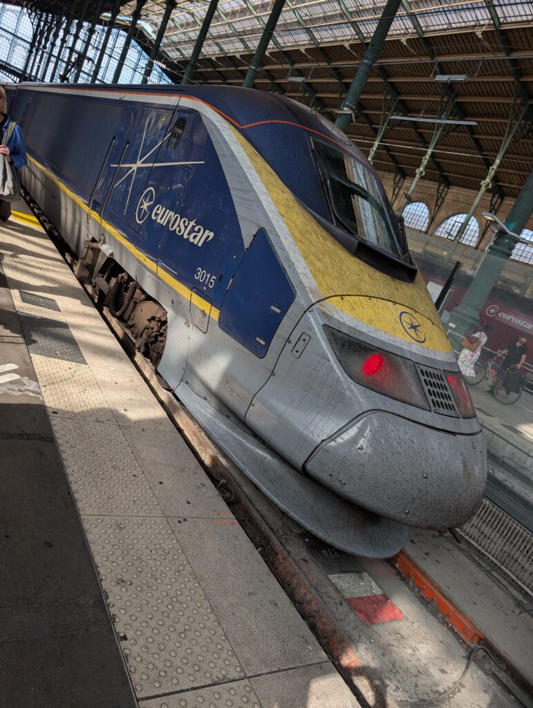
Following my recent post on the St Pancras train shed, here is a look at what rolls beneath it. While waiting on the platform I photographed the running gear of a Eurostar e300, including power car 3015 and the articulated joint between two trailer cars. A high-speed bogie is a rolling laboratory of vibration engineering: multi-stage isolation, half a dozen hydraulic dampers per bogie in several orientations, pneumatic springs with self-leveling, and a stability problem, hunting, that is one of the classic self-excited oscillations in all of mechanical engineering. This post walks through the suspension and shock absorber architecture visible in the photographs.
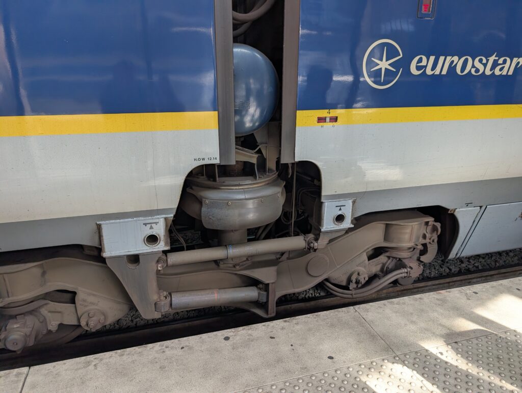
Figure 1: Articulated trailer bogie with secondary suspension and horizontal dampers
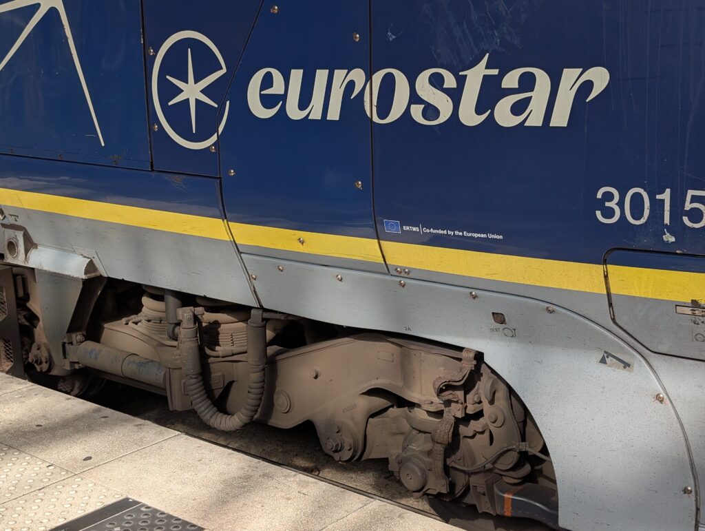
Figure 2: Power car 3015 bogie with primary coil springs
The Eurostar e300
The e300, originally British Rail Class 373, is the TGV TransManche Super Train built by GEC-Alsthom in 1992 to 1996 for Channel Tunnel service: a power car at each end and an articulated rake of trailer cars between, about 394 m in original full-length form, with a 300 km/h service speed. These are the elder statesmen of the fleet, now more than three decades old, refurbished and retrofitted with ERTMS signaling (the European Union co-funding sticker is visible beside the running number), and operating alongside the newer Siemens e320 sets while Eurostar prepares its next-generation fleet. Three decades of service at 300 km/h is a fatigue and wear testament in its own right, and much of the credit belongs to the suspension.
Two-Stage Suspension Architecture
Like virtually all high-speed rail vehicles, the e300 uses two suspension stages in series:
Primary suspension connects each axlebox to the bogie frame. On the power car bogie in the photo, the coil springs over the axleboxes are clearly visible, paired with vertical hydraulic dampers. The primary stage is relatively stiff. Its jobs are to control the wheelset, distribute wheel loads, and filter the high-frequency input from rail roughness, joints, and switches before it reaches the bogie frame. The unsprung mass below the primary springs, wheelset, axleboxes, brake discs, and (on power cars) part of the drive, is the quantity every bogie designer fights to minimize, since dynamic wheel-rail forces scale with it.
Secondary suspension connects the bogie frame to the carbody. This is the soft stage, tuned to give the carbody a bounce natural frequency near 1 Hz, and it carries the ride comfort mission. The large bellows element at the articulated joint in the first photo is the heart of the secondary stage, with the blue-gray spheroid above it serving as an air reservoir for the pneumatic system. Air suspension brings three gifts: a low natural frequency without enormous static deflection, self-leveling via valves that hold ride height constant from empty to crush-loaded (which also keeps the natural frequency roughly constant, since stiffness rises with payload), and good structure-borne noise isolation. An internal rubber emergency spring carries the load if the air system fails.
The series arrangement is a textbook two-stage isolator. For base excitation of a single stage, the transmissibility is
\[ T(f) = \sqrt{ \frac{1 + \left( 2\zeta \frac{f}{f_n} \right)^2 }{ \left( 1 – \frac{f^2}{f_n^2} \right)^2 + \left( 2\zeta \frac{f}{f_n} \right)^2 } } \]with isolation beginning above \( \sqrt{2} f_n \). A secondary stage at 1 Hz is attenuating by about 1.4 Hz and rolling off steeply through the frequencies where humans are most vibration-sensitive, the 4 to 8 Hz band emphasized by the ISO 2631 vertical weighting. Two stages in series buy a steeper combined rolloff than either alone, at the cost of an interposed mass (the bogie frame) whose own modes must be managed. There is one more constraint the aerospace isolation designer rarely faces: the carbody of a 20-plus meter rail vehicle has its first vertical bending mode near 8 to 12 Hz, and the suspension must avoid pumping energy into it. Keeping the secondary bounce frequency near 1 Hz maintains a comfortable octave-plus separation.
The Damper Inventory
The horizontal cylinders flanking the articulation in the first photo are the visible members of a substantial damper population. A representative inventory for a high-speed bogie:
| Damper | Orientation | Function |
|---|---|---|
| Primary vertical | Vertical, axlebox to frame | Damp wheelset and primary bounce modes; control wheel load variation |
| Secondary vertical | Vertical, frame to body | Damp carbody bounce and pitch (~1 Hz) |
| Secondary lateral | Lateral, frame to body | Damp carbody sway and lower sway modes |
| Yaw (anti-hunting) | Longitudinal, frame to body | Resist bogie yaw oscillation; raise critical speed |
| Inter-car / articulation | Longitudinal or lateral between bodies | Damp relative car motions in an articulated rake |
These are hydraulic viscous dampers with deliberately shaped force-velocity characteristics, often blow-off valves that soften the response at high velocity to limit force transmission over severe inputs, conceptually the same nonlinearity conversation we have in shock isolation. Dampers are also the suspension’s consumable: gas absorption, seal wear, and oil degradation soften the characteristic over service, which is why fleets track them through overhaul schedules and, increasingly, through condition monitoring of bogie accelerations, an SHM philosophy directly analogous to the monitoring box in my St Pancras post.
Hunting and the Yaw Damper
The most interesting dampers on the vehicle are the longitudinally mounted yaw dampers, and they exist because of a beautiful instability. A railway wheelset is coned: the rolling radius increases toward the flange. Displace the wheelset laterally and the outer wheel rolls on a larger radius than the inner, steering the wheelset back toward center, past center, and out to the other side. The result is a kinematic sinusoidal path first analyzed by Klingel in 1883, with wavelength
\[ \lambda = 2\pi \sqrt{ \frac{r_0 \, e}{2\gamma} } \]where \( r_0 \) is the wheel rolling radius, \( 2e \) is the lateral spacing of the contact points (about 1.5 m for standard gauge), and \( \gamma \) is the effective conicity. For \( r_0 = 0.46 \) m, \( e = 0.75 \) m, and a moderately worn conicity of \( \gamma = 0.15 \):
\[ \lambda = 2\pi \sqrt{ \frac{(0.46)(0.75)}{0.30} } \approx 6.7 \;\text{m} \]At 300 km/h (83.3 m/s), that wavelength is traversed at
\[ f = \frac{V}{\lambda} = \frac{83.3}{6.7} \approx 12 \;\text{Hz} \]The kinematic motion is not itself unstable, but couple it to the creep forces at the wheel-rail contact and the yaw inertia of wheelset and bogie, and above a critical speed the coupled wheelset-bogie yaw/lateral mode extracts energy from the forward motion and grows: hunting, a genuine self-excited oscillation in the same family as flutter and oil whirl. The critical speed falls as conicity rises, and conicity rises with wheel and rail wear, so a vehicle that is stable when new can become marginal late in a wheel turning interval. The yaw dampers attack the instability directly by dissipating energy in the bogie yaw degree of freedom, and they are the single most important suspension element in setting the critical speed of a 300 km/h vehicle. Their tuning is a compromise: too little yaw restraint invites hunting; too much stiffens the bogie against rotating in curves and grinds the wheel flanges and high rail. Stability and curving pull the designer in opposite directions, and every high-speed bogie is a negotiated settlement between them.
The Articulation
The first photograph shows a distinctly TGV-family feature: the trailer cars share a common bogie at each junction, a Jacobs bogie, with the carbody ends resting on it and the secondary suspension at the articulation. The arrangement roughly halves the trailer bogie count, reducing mass, drag, cost, and the number of suspension elements to maintain. It also places passengers away from the bogies rather than over them, which helps both noise and ride. And it has a crashworthiness dividend demonstrated in TGV derailment history: an articulated rake tends to stay coupled and upright rather than jackknifing, because adjacent carbodies restrain each other through the shared bogie. The price is axle load (each Jacobs bogie carries the ends of two cars), a fixed trainset formation, and the need for depot equipment that can lift an articulated rake.
Ride Quality Metrics
The suspension’s report card is written in standards. European practice evaluates ride comfort per EN 12299, using frequency-weighted RMS accelerations measured in the carbody, the descendant of the classic Sperling ride index Wz, while ISO 2631 supplies the underlying human-response weightings, the same weightings that appear in building vibration work (BS 6472 in the St Pancras post) and in my seating and biodynamics discussions in the vibration courses. The engineering chain is pleasingly complete: rail roughness PSD in, through primary and secondary transmissibilities, weighted carbody acceleration out, a random vibration problem from end to end, and one that responds to exactly the PSD and transmissibility toolset this blog exists to teach.
Closing Thoughts
Next time you board a high-speed train, spare a glance below the yellow stripe. The coil springs, bellows, and unglamorous gray cylinders down there embody a full curriculum: two-stage isolation, transmissibility, self-excited instability, nonlinear damping, condition monitoring, and a thirty-year fatigue demonstration at 300 km/h. The e300 fleet is approaching retirement, and when these sets finally stand down, their bogies will have earned a place in the engineering museums alongside the locomotives they succeeded.
My free ebooks on shock, vibration, and fatigue are available here: https://blog.vibrationdata.com/2025/11/27/toms-ebooks/
References
- Iwnicki, S. (ed.), Handbook of Railway Vehicle Dynamics, CRC Press, 2006.
- Wickens, A.H., Fundamentals of Rail Vehicle Dynamics: Guidance and Stability, Swets & Zeitlinger, 2003.
- Klingel, W., “Über den Lauf der Eisenbahnwagen auf gerader Bahn,” Organ für die Fortschritte des Eisenbahnwesens, 1883.
- EN 12299, Railway Applications – Ride Comfort for Passengers – Measurement and Evaluation, European Committee for Standardization.
- ISO 2631-1, Mechanical Vibration and Shock – Evaluation of Human Exposure to Whole-Body Vibration, International Organization for Standardization.
- Garg, V.K., Dukkipati, R.V., Dynamics of Railway Vehicle Systems, Academic Press, 1984.