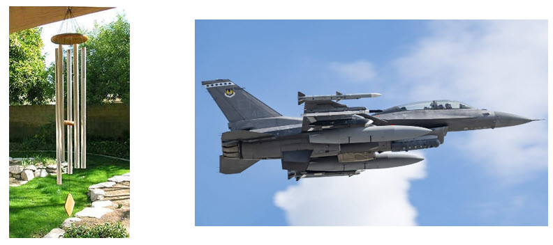
A slender store hanging under a fighter wing sits in an acoustic field near 164 dB overall. A wind chime tube hanging from a porch beam sits in an acoustic field near 40 dB. The store is asked to survive; the chime is asked to sing. One is 361 kg of steel and the other is 166 grams of aluminum. And yet, as beams in bending, the two objects behave in almost exactly the same way, for exactly the same reasons, and the reasons run in both directions at once.
That two-way character is the part that usually gets dropped. We ask “how much does the acoustic field excite the structure?” and we answer it with a joint acceptance function. Separately, we ask “how much sound does the vibrating structure make?” and we answer that with a radiation efficiency. These are treated as two different problems in two different chapters. They are not. They are the same number, read left to right or right to left.
This post works through both directions for beam bending modes, and then uses the missile and the wind chime as a matched pair. The pair is instructive precisely because the two objects are nearly the same shape. Their slenderness ratios are 16.4 and 19.7. Whatever separates them, it is not geometry.
One Coupling Number, Read in Either Direction
Start with the forward problem. A pressure field with spectral density $S_p(f)$ acts on a body of area $A$. The generalized force spectral density delivered to mode $n$ is
$$S_{F_n}(f) \;=\; S_p(f)\; A^2\; j_n^2(f)$$where $j_n^2(f)$ is the joint acceptance: the normalized double integral of the pressure cross-spectral density against the mode shape, over the surface, twice. It is a pure spatial-matching number between zero and one. It equals one only when the pressure is in phase everywhere the mode wants to move, and it collapses toward zero whenever the pressure pattern and the mode pattern disagree in space.
Now the reverse problem. The same mode, vibrating with mean square surface velocity $\langle v^2 \rangle$ over the same area, radiates sound power
$$\Pi \;=\; \rho c \, S \, \sigma_n(f) \, \langle v^2 \rangle$$where $\sigma_n(f)$ is the radiation efficiency, again a number between zero and one, again a pure spatial-matching quantity. It equals one when the structural surface pushes the fluid the way a rigid piston would, and collapses toward zero when neighboring patches of the surface move in opposite directions and simply shuffle fluid back and forth instead of launching a wave.
Those two paragraphs describe the same integral. In statistical energy analysis this is written as the consistency relation between coupling loss factors, $n_1 \eta_{12} = n_2 \eta_{21}$, with $\eta_{21} = \rho c S \sigma/(\omega M)$ appearing on the structure-to-room side. Because $\eta_{21}$ carries $\sigma$, and because consistency forces $\eta_{12}$ to carry the same $\sigma$, the radiation efficiency governs how strongly the reverberant field drives the structure as well. For a diffuse field the two coupling descriptions are related, up to a constant of order unity that depends on baffling conventions, by
$$j_n^2 \;\sim\; \frac{\sigma_n \, \lambda^2}{4 \pi S}$$A structure that will not radiate cannot be driven by sound. A structure that radiates well is also easy to drive with sound. There is no design in which one direction is strong and the other is weak.
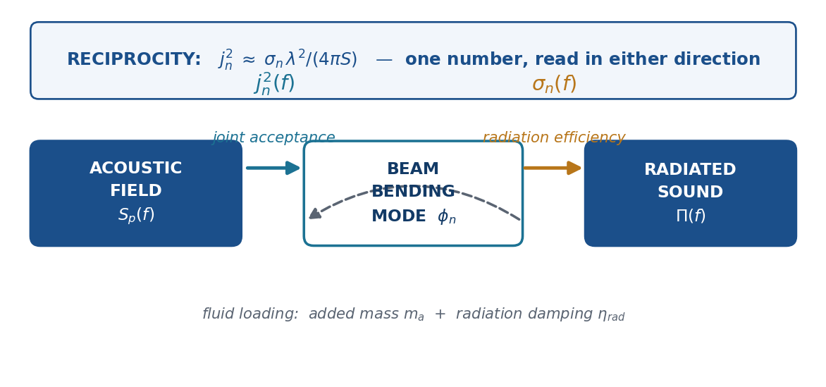
Figure 1. The two directions and the feedback path. Joint acceptance and radiation efficiency are the same spatial-matching integral. The dashed path is fluid loading, which returns added mass and radiation damping to the structure.
Two Ways for a Slender Beam to Cancel
For a slender body there are two independent cancellation mechanisms, and both must be defeated before coupling reaches unity in either direction.
Around the circumference. When the acoustic wavelength is much larger than the diameter, the pressure wraps the body nearly in phase. A uniform pressure on a closed cylinder is a hoop load, not a transverse resultant. The lateral force survives only as the small pressure difference across the diameter, and the coupling scales as
$$j_{circ} \;\approx\; \min\!\left(1, \; \frac{kD}{2}\right), \qquad k = \frac{2\pi f}{c}$$Read backwards, this is the classical statement that a laterally oscillating cylinder is an acoustic dipole. The near field simply circulates around the body from the advancing side to the retreating side, and very little escapes as a propagating wave.
Along the span. When the acoustic wavelength is much smaller than the length, the field reverses sign many times along the body, and adjacent patches push in opposite directions. In the diffuse-field limit the surviving fraction goes as
$$j_{span} \;\approx\; \min\!\left(1, \; \sqrt{\frac{\pi}{kL}}\right)$$The product of the two terms is squeezed from both sides and peaks near $kD = 2$, with a ceiling of
$$j_{max} \;=\; \sqrt{\frac{\pi D}{2L}}$$Reaching unity requires $kD \geq 2$ and $kL \leq \pi$ simultaneously. Since $kL/kD = L/D$, that demands a slenderness ratio at or below about 1.6. A compact body qualifies. A slender one never does. Both objects in this post are more than ten times too slender, in both directions, forever.
The Wavenumber Picture Is the Honest One
The two-term product is a useful envelope, but the physics is cleaner in the wavenumber domain. Take the bending mode shape, transform it along the axis, and look at where its energy sits in $k_z$. The fluid can only exchange propagating energy with the supersonic window $|k_z| < k$, where $k = \omega/c$ is the acoustic wavenumber. Content outside that window is evanescent: it produces near-field circulation and nothing else.
The bending wavenumber of a beam is
$$k_b \;=\; \left(\frac{\omega^2 m’}{EI}\right)^{1/4}$$which grows only as the square root of frequency, while $k$ grows linearly. The two cross at the beam coincidence frequency
$$f_c \;=\; \frac{c^2}{2\pi \sqrt{EI/m’}}$$Below $f_c$ the bending wave is subsonic and the mode’s wavenumber peak sits outside the acoustic window; only the finite-length leakage skirts reach in. Above $f_c$ the peak sits inside the window and the coupling is strong. That single crossing is the sharpest difference between our two objects, and it runs the opposite way from most engineering intuition: a heavy, stiff, long beam has a low coincidence frequency, because its bending waves are fast.
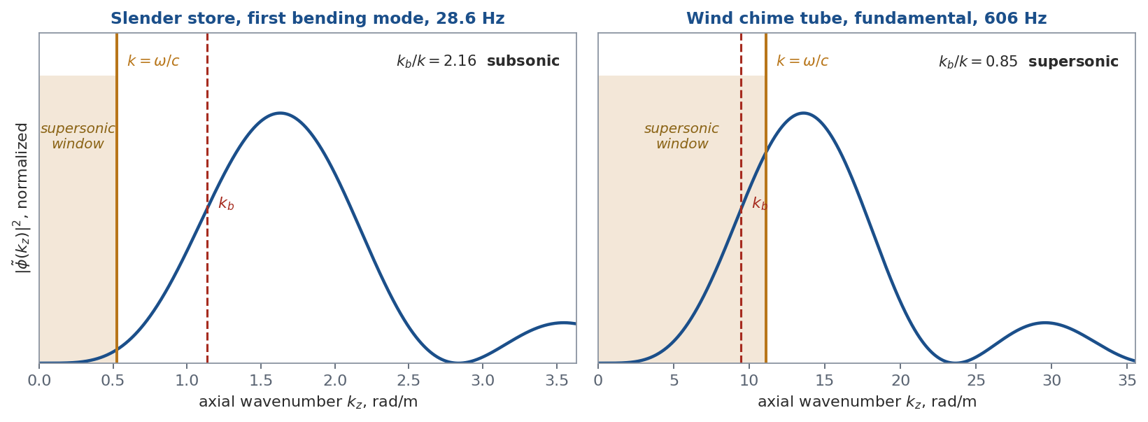
Figure 2. Axial wavenumber content of the first bending mode of each body, with the supersonic window shaded. The store’s mode-1 content lies almost entirely outside the window. The chime’s fundamental sits with a large fraction inside it.
The Store on the Wing
Take a representative slender store carried externally on a generic fighter wing: 164 in long, 10 in in body diameter, 795 lb, with its first seven fixed-base bending modes spanning 28.6 to 155 Hz. The external carriage acoustic environment is 164 dB overall, which is 0.4597 psi rms; an internal weapon bay condition is 147 dB, or 0.0649 psi rms. The projected side area is 1640 in². The speed of sound is 13,500 in/sec, so $kD = 1$ at 215 Hz and coupling peaks at $kD = 2$, which is 430 Hz.
Across the entire bending band, joint acceptance runs from 0.067 to 0.186, that is $-23.5$ to $-14.6$ dB. The acoustic field pushes hardest where the beam does not respond, and the beam responds where the acoustic field cannot push. The two windows do not overlap.
Working the numbers band by band, with the pressure spectral density formed from the third-octave levels, the corrected net transverse force over 20 to 160 Hz is 46 lbf rms at 164 dB. The fully correlated bound over the same band, which is what you get if you set $j = 1$, is 304 lbf. The internal bay case at 147 dB gives 6.5 lbf. Against roughly 3000 lbf rms of inertial load already carried in the flight-measured vibration specification, 46 lbf is 1.5 percent, and at a fatigue exponent of $m = 3$ that lands in the fourth decimal place of damage.
Here is the useful cross-check, and the reason to care about the two-way framing. Run the problem backwards. Compute the radiation efficiency of that same body in rigid transverse translation, using the exact Hankel-function dipole impedance of a cylinder integrated over the supersonic window, then convert $\sigma$ into an implied joint acceptance through the reciprocity relation. The two curves are derived from entirely different starting points, one from blocked pressure on a rigid cylinder and one from radiated power, and they land on the same shape, the same peak region, and within a factor of about two in amplitude across the modal band.
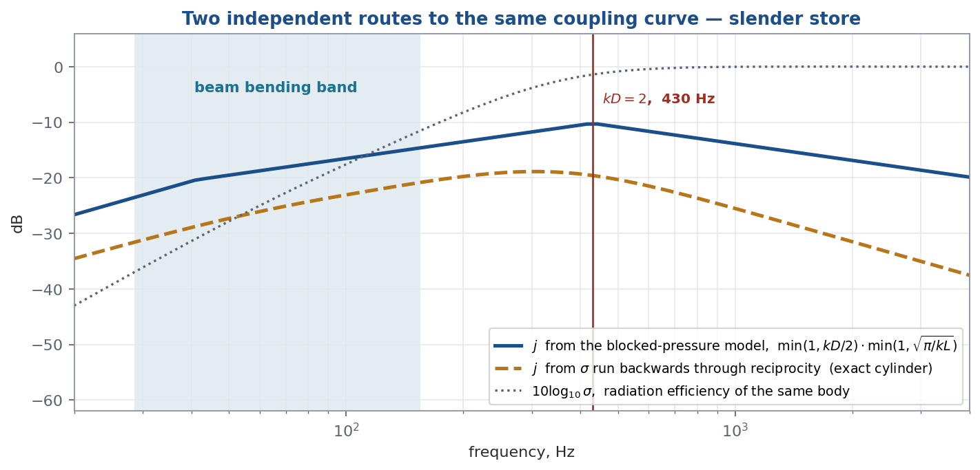
Figure 3. Joint acceptance for the store from two independent routes. Both peak near $kD = 2$ and both fall away on either side. The dotted curve is the radiation efficiency that produced the dashed one.
Practical consequence. If a proposed acoustic force is being layered on top of a measured vibration specification, the acoustic field was physically present during those flight measurements and is already embedded in the envelope. Adding a separate acoustic force re-applies the same excitation a second time. A common error compounds this: computing the force as pressure times cross-sectional area rather than projected side area, which is low by about 26 dB, while simultaneously setting $j = 1$, which is high by 15 to 24 dB. The two errors partially cancel and the broadband total looks plausible. It does not hold band by band, and arriving near the right answer through offsetting errors is much harder to defend than a clean, documented exclusion.
The Wind Chime
Now the porch. Take a 25.4 mm outside diameter aluminum tube with a 1.65 mm wall, 0.50 m long. That gives $A = 123$ mm², $I = 8726$ mm⁴, $EI = 602$ N·m², and a mass of 166 grams. Hung on a cord, it is a free-free beam, and its bending frequencies fall at 606, 1671, 3275, 5414 and 8087 Hz. The ratios are 1 : 2.76 : 5.40 : 8.93, which is the familiar inharmonic chime series, and the reason a chime does not sound like a flute.
Two design details follow from the mode shapes rather than from acoustics. The cord passes through the tube at 0.224 L, which is the node of the fundamental, so the support does not damp the mode you most want to hear. And the clapper strikes near mid-span, which is an antinode of the fundamental and of the third partial.
The coincidence frequency of this tube is 440 Hz. Its fundamental is 606 Hz. Every partial in the audible series lies above coincidence. That is not a coincidence in the other sense: to make an audible chime, the bending waves in the tube have to be supersonic in air.
The computed radiation efficiencies follow directly. The fundamental manages $\sigma = 3.4 \times 10^{-4}$, because it clears the spanwise cancellation but still has $kD = 0.28$ and pays the full circumferential dipole penalty. By the third partial, $kD = 1.52$ and $\sigma$ has climbed to 0.42. By the fourth, $\sigma = 0.85$. The tube is essentially a piston at the top of its range.
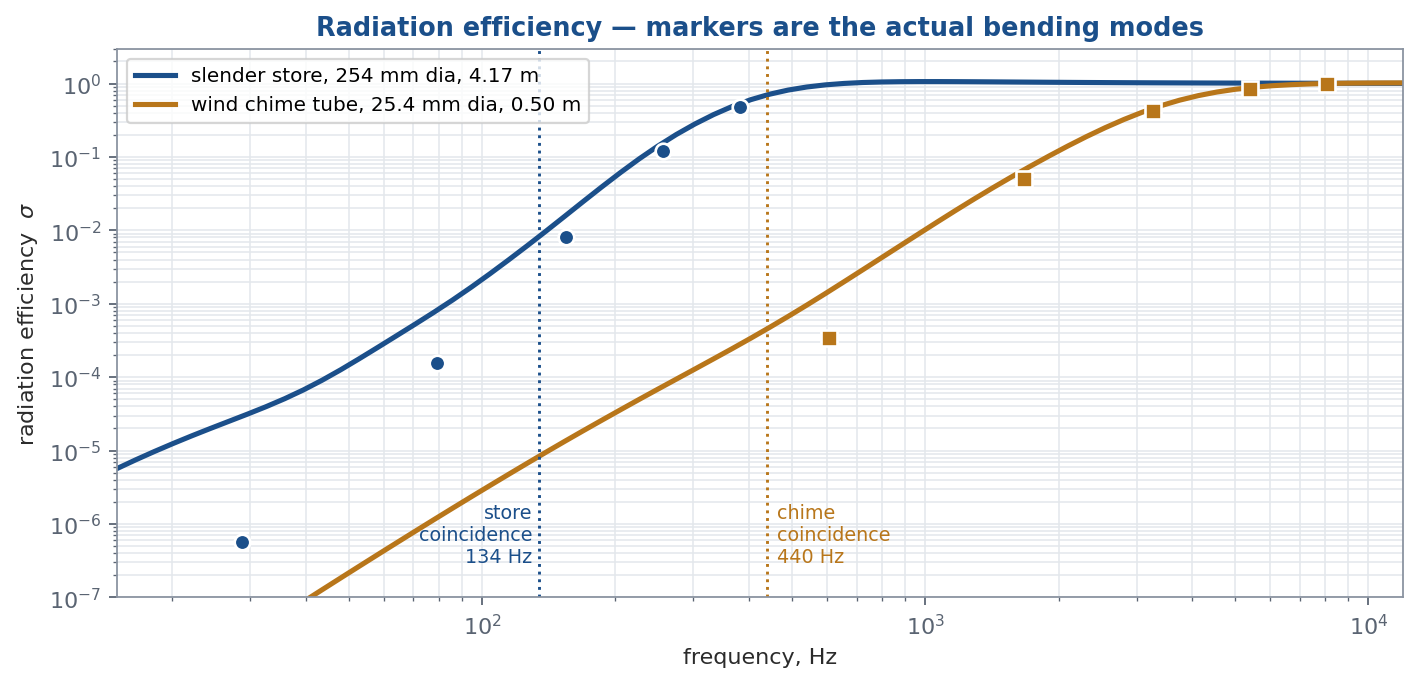
Figure 4. Radiation efficiency for both bodies, with markers at their actual bending modes. The curves have the same shape; the modes land in completely different places on them.
Two Nearly Identical Shapes, Two Different Lives
| Quantity | Slender store | Wind chime tube |
|---|---|---|
| Length | 4.17 m | 0.50 m |
| Diameter | 254 mm | 25.4 mm |
| Slenderness $L/D$ | 16.4 | 19.7 |
| Mass | 361 kg | 0.166 kg |
| First bending mode | 28.6 Hz | 606 Hz |
| Beam coincidence $f_c$ | 134 Hz | 440 Hz |
| $f_1 / f_c$ | 0.21, subsonic | 1.38, supersonic |
| $kD$ at $f_1$ | 0.13 | 0.28 |
| $\sigma$ at $f_1$ | $5.6 \times 10^{-7}$ | $3.4 \times 10^{-4}$ |
| $\sigma$ at the top mode shown | 0.48 at 382 Hz | 0.99 at 8087 Hz |
| Total loss factor | $\approx 0.05$ | $\approx 2 \times 10^{-4}$ |
| $\eta_{rad}/\eta_{total}$ at $f_1$ | $2 \times 10^{-7}$ | 0.04 |
| Excitation | 164 dB distributed field | point impulse from a clapper |
| Sound is | a nuisance to be excluded | the entire product |
What Actually Separates Them Is the Damping Budget
Here is the result that surprised me when I ran it. The two radiation efficiencies at the fundamental differ by a factor of about 600, which sounds decisive until you notice that both are small numbers with no absolute meaning. What matters is the fraction of the total loss budget that radiation represents. Convert $\sigma$ into a radiation loss factor,
$$\eta_{rad} \;=\; \frac{\rho c \, \sigma \, S}{\omega M}$$and compare it against everything else that removes energy from the mode. The store is bolted through lugs and an adapter into a pylon, and its structural and joint damping is on the order of $\eta = 0.05$. The chime is a single unjointed extrusion hanging on a cord at a node, and its total loss factor is on the order of $2 \times 10^{-4}$, roughly 250 times smaller.
For the store, $\eta_{rad}$ at the first bending mode is $1.2 \times 10^{-8}$, which is two ten-millionths of the loss budget. Even at 382 Hz, where $\sigma$ has reached 0.48, radiation still carries only 1.5 percent of the damping. Acoustic radiation is invisible in that structure at every frequency of engineering interest.
For the chime, $\eta_{rad}$ at the fundamental is $8.9 \times 10^{-6}$ against a total near $2 \times 10^{-4}$, so radiation carries about four percent of the loss. By the second partial, $\eta_{rad} = 4.8 \times 10^{-4}$ and radiation has become the dominant loss mechanism. By the third and fourth partials it exceeds everything else by an order of magnitude.
That single fact predicts something everyone has heard. If you compute the reverberation time from radiation alone, $T_{60} = 2.2/(f \eta_{rad})$, the fundamental would ring for 406 seconds, the second partial for 2.8 seconds, the third for 0.33 seconds, and the fourth for 0.16 seconds. Strike a chime tube and the bright metallic attack vanishes in a fraction of a second while the low hum carries on for many seconds. The bright partials die first because they are the only ones efficient enough to convert their energy into sound.
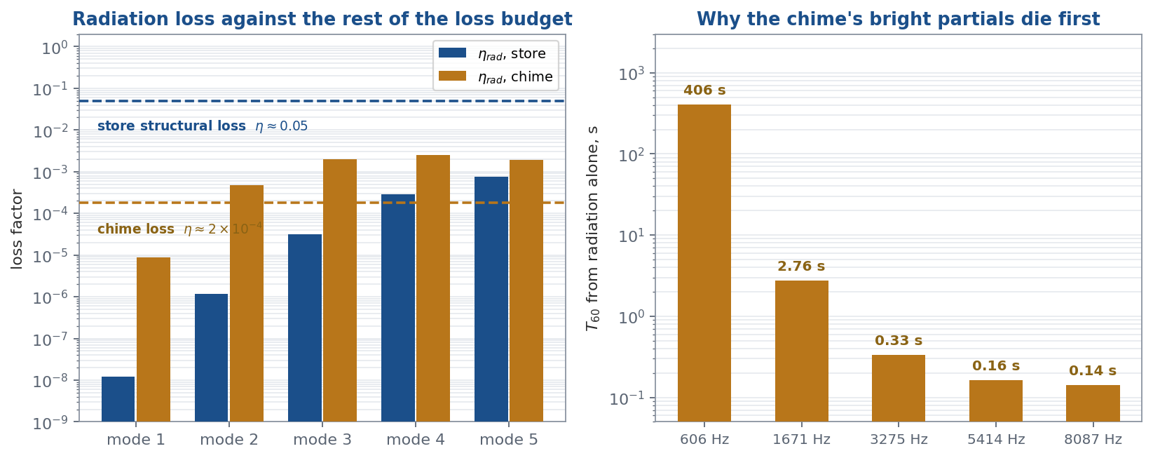
Figure 5. Left: radiation loss factor against the rest of the loss budget for both bodies. Right: decay time of each chime partial if radiation were the only loss. Mode numbers refer to each body’s own bending series.
The general lesson. Radiation efficiency alone never tells you whether acoustic coupling matters. It has to be compared against the structure’s other loss paths and, on the excitation side, against the structure’s other load paths. A poorly radiating mode in a very lightly damped structure can still be acoustically dominated. A moderately radiating mode in a heavily jointed structure is acoustically irrelevant. The coupling number is only half the question.
The Other Half: a Point Force Never Pays the Joint Acceptance Penalty
There is a second asymmetry, and it is the reason the wind chime works at all despite terrible coupling in both directions. A distributed field has to match a shape. A point force does not.
The generalized force from a concentrated load at $x_0$ is simply $F \phi_n(x_0)$. With the mode shape normalized to unit mean square, $|\phi_n|$ reaches 2.0 at the ends of a free-free beam and is of order one nearly everywhere except at the nodes. A clapper cannot fail to couple. It cannot cancel against itself, because there is nothing for it to cancel against.
The distributed case is far worse than the two-term envelope suggests, and for the chime it is worse in an exact way. A free-free elastic mode is orthogonal to both rigid-body translation and rigid-body rotation, which means
$$\int_0^L \phi_n(x)\,dx \;=\; 0 \qquad \text{and} \qquad \int_0^L x\,\phi_n(x)\,dx \;=\; 0$$for every elastic mode. A spatially uniform pressure therefore produces exactly zero generalized force on any bending mode of a hanging tube. Not small: zero. The leading nonzero term is second order in $kL$, which is why the low-frequency end of the chime’s joint acceptance is even weaker than the envelope formula predicts.
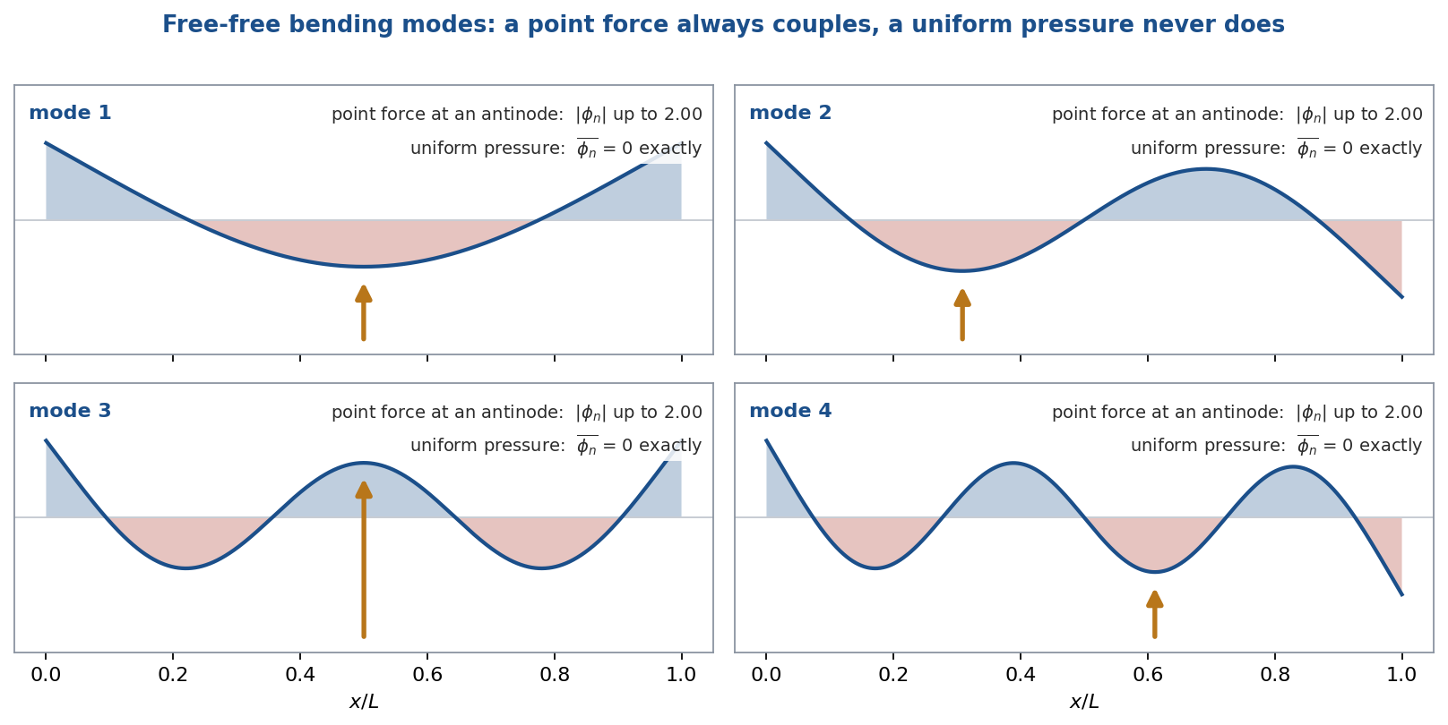
Figure 6. Free-free bending modes with unit mean-square normalization. The arrow marks an interior antinode where a clapper couples at order one. The positive and negative areas of every mode are exactly equal, so a uniform pressure couples not at all.
It is worth putting a number on the reverse question, since it is the one people ask when they first meet reciprocity: can you ring a wind chime by shouting at it? Working backwards from the radiation efficiency, and ignoring the orthogonality suppression above so the answer is generous, you would need roughly 100 dB of pure tone held exactly on 606 Hz to drive the tube to a velocity you would notice across the room. Ordinary conversation is 60 dB and spread across the whole band, of which the fraction inside the tube’s high-Q resonance is a small sliver. Nobody has ever rung a wind chime with their voice, and the joint acceptance function says why.
The Feedback Path: Fluid Loading
The dashed arrow in Figure 1 is the third interaction, in which the fluid modifies the structure it is coupled to. It contributes added mass, which shifts frequencies down, and radiation damping, which we have already covered.
In air, added mass is negligible for both bodies. The displaced-fluid mass per unit length is 0.18 percent of the chime’s linear mass and 0.07 percent of the store’s, giving frequency shifts of 0.09 and 0.04 percent. Neither is worth modeling.
Change the fluid and the conclusion inverts completely. In water the same displaced mass is 152 percent of the chime tube’s linear mass and 58 percent of the store’s, which would drop their bending frequencies by 37 and 21 percent respectively before any other effect is considered. This is why a torpedo is a different analysis from a missile even when the two are geometrically similar: heavy fluid loading makes the coupling term a first-order participant in the eigenvalue problem rather than a post-processing step. In air it is safe to solve the structure first and the acoustics afterward. In water it is not.
Where the Acoustic Energy Actually Goes
Excluding acoustics from a beam bending model is not the same as excluding acoustics. The energy is still there; it goes somewhere else.
The joint acceptance suppression derived above applies to the net transverse resultant on a slender body. It says nothing about local response. Fins, control surfaces and skin panels are thin, flat, and low in surface mass density. Their panel modes fall in the hundreds of hertz to low kilohertz, right inside the flat portion of the acoustic spectrum, and they respond through local modal coincidence with the pressure field rather than through any body-level resultant. A store with a 44 in wingspan on a 10 in body has 17 in of exposed semi-span per fin, and that is a genuine acoustic fatigue problem.
The correct fork is to state explicitly:
- For the bending-moment fatigue and crack-growth spectrum, exclude the acoustic field and document the joint acceptance basis in two lines.
- For fin, skin-panel and equipment qualification, use statistical energy analysis or an empirical acoustic-to-vibration method on a separate shell-level model.
- Never a beam model, in either case. The store is below its 6366 Hz ring frequency throughout the spectrum, so shell response is stiffness controlled and needs shell kinematics to represent it.
One more two-way interaction deserves mention because it does not obey the weak-coupling logic above at all. An internal weapon bay with the doors open supports a Rossiter feedback loop, in which shear-layer vortices, an acoustic wave travelling back upstream, and the cavity geometry lock into a self-sustaining tone. That is a genuine strong two-way coupling between the flow, the acoustic field and the structure, and it is not governed by joint acceptance in any useful sense. I wrote that one up separately.
Basis and Caveats
- The two-term joint acceptance expressions are engineering approximations. They capture the correct trend and magnitude but are not a substitute for the full cross-spectral density integral against the mode shapes. The circumferential term is the classical dipole result for a rigid cylinder in a transverse wave, valid for $kD$ below about 2. The spanwise term is the diffuse-field decorrelation form; a plane wave at grazing incidence gives a sinc form with the same envelope but with a visible coincidence peak that the diffuse average smooths away.
- The reciprocity constant relating $j^2$ to $\sigma$ depends on baffling and field-type conventions. My numerical check on the store agreed in shape and peak location and within a factor of about two in amplitude, which is the right expectation for a relation of this kind. Use it as a cross-check, not as a substitute for the direct calculation.
- Radiation efficiencies here come from the exact dipole surface impedance of an infinite cylinder, integrated over the modal wavenumber spectrum of a finite free-free beam. That combination handles the finite-length leakage correctly but idealizes the end conditions and ignores the fins entirely.
- The store’s bending stiffness was backed out of the reported 28.6 Hz first mode. Radiation depends on wavenumber content, which is set mostly by mode order and length rather than by end conditions, so the idealization is mild for this purpose. It would not be mild for a stress calculation.
- The chime’s total loss factor of $2 \times 10^{-4}$ is a representative value chosen to give a physically sensible ring-down; real chimes vary widely with alloy, cord material and hang point. The radiation loss factors are computed, not assumed, and they are the part of that budget that does not depend on the guess.
- The inertial comparison for the store uses the 795 lb store weight. A modal model will report a larger participating weight including adapter and lug hardware, so state the reference mass wherever a g-level is quoted.
Closing
Two slender tubes, nearly the same slenderness, both bending, both coupled to air through the same integral read in two directions. Neither one couples well. The store’s first bending mode radiates at $\sigma = 5.6 \times 10^{-7}$; the chime’s fundamental manages $3.4 \times 10^{-4}$. Both are terrible radiators by any absolute standard, and by reciprocity both are correspondingly hard to drive with sound.
What separates them is not the coupling. It is what the coupling is measured against. For the store the comparison is 3000 lbf of inertial load and a loss factor of 0.05, so a 46 lbf acoustic resultant disappears into the fourth decimal place of fatigue damage and radiation disappears entirely from the damping budget. For the chime the comparison is a loss factor 250 times smaller and a detector — the human ear — that is one of the most sensitive instruments in existence. Under that comparison, $\sigma = 3.4 \times 10^{-4}$ is not a small number. It is a wind chime.
A full set of free ebooks covering shock and vibration response spectra, statistical energy analysis, acoustics, stress-velocity and fatigue is available here. The companion post on cavity tones and the Rossiter feedback loop covers the strongly coupled case that this analysis deliberately sets aside, and the post on Nastran SOL 111 versus SOL 112 covers what to do once the force spectral density is in hand.