The pair below sits on South Bayshore Drive in Coconut Grove, Miami, on the site of the old Grand Bay Hotel. Bjarke Ingels Group designed them, DeSimone Consulting Engineers made them stand up, and they were completed in 2016. Each tower rotates a total of 38 degrees from base to crown. They are usually discussed as architecture. They are more interesting as a structural dynamics problem, because they are a rare case where the load that governs the lateral system is not the hurricane. It is gravity.
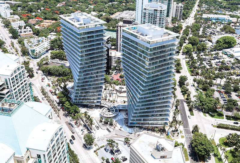
Figure 1. Grove at Grand Bay, Coconut Grove, Miami. Two 20-story towers on a two-story podium, each rotating 38 degrees over its height. Image source to be credited.
The word irregularity does double duty in our field. In ASCE 7 it means a plan or vertical discontinuity that triggers extra seismic requirements. In random vibration it means $\gamma = n_0/n_p$, the ratio of zero upcrossings to peaks, which tells you how narrowband a process is. These towers are a good excuse to look at both, because the code sense turns out to cost almost nothing here and the spectral sense turns out to matter more than you would guess.
The Twist Is Structural, Not Cosmetic
Plenty of towers look twisted because the slab edge and the curtain wall rotate while the columns stay plumb. That is a cladding problem. These are not that. Published accounts of the project describe 30-inch-diameter concrete columns, placed mostly on the perimeter, that slant so that each column occupies the same position relative to each rotating floor plate. The core walls are the only consistently vertical structural elements in the building, and there are no interior column lines. Post-tensioned flat slabs span from the core to the perimeter and cantilever ten to sixteen feet beyond the window wall to form the balconies you can see in Figure 1.
Once the columns rake, every one of them carries a horizontal component of its own gravity load. That is the whole story of this building.
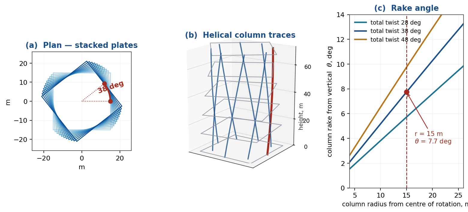
Figure 2. Geometry of a generic twisting tower. Every perimeter column is a helix, and the rake angle grows linearly with distance from the centre of rotation.
The rake angle follows directly from the geometry. For a total rotation $\beta$ over height $H$, a column at radius $r$ from the centre of rotation rakes at
$$\theta = \arctan\!\left(\frac{r\,\beta}{H}\right)$$
Note that $\theta$ depends on radius, not on story height. Corner columns rake harder than mid-face columns on the same tower, which is exactly why the usual corner-column layout had to be abandoned on this project. Figure 2(c) shows the sensitivity. Everything that follows uses a generic model built to represent this class of building. It is not the actual design, and I have no access to those drawings. The parameters are in Table 1.
| Parameter | Value |
|---|---|
| Stories above podium, story height | 20 at 3.66 m, tower height 73.2 m (240 ft) |
| Total rotation, rotation per floor | 38 deg, 1.90 deg per floor |
| Nominal plan, column ring radius | 30 m square, 12 columns at r = 15 m |
| Tangential travel per floor | 0.497 m, giving $\tan\theta$ = 0.136, $\theta$ = 7.7 deg |
| Sustained gravity, D + 0.25L | 10.5 kPa on 850 m², 8.05 MN per floor |
| Fraction to perimeter columns | 65 percent, 0.436 MN per column per floor |
| Core | 12 m by 8 m box, 0.76 m (30 in) walls, 55 MPa |
Table 1. Generic twisting tower used for the worked example throughout this post.
Where a Raked Column Sends Its Load
Take one column. At each floor it picks up an increment of gravity load $w$, and because it is inclined, that increment arrives at the next floor down with a horizontal component $w\tan\theta$. The slab has to take that horizontal force in its own plane and carry it somewhere. In this building the only place it can go is the core.
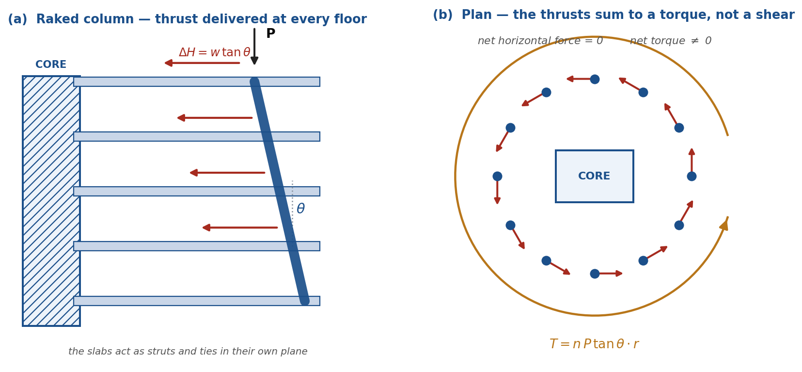
Figure 3. The gravity load path. Each floor delivers $w\tan\theta$ per column into the slab, and because every column rakes in the same rotational sense, the thrusts cancel as a force and add as a torque.
Now look at the plan. All the columns rake in the same rotational sense, so all the thrusts are tangential and all point the same way around the ring. Their vector sum is zero. Their moment sum is not. The torque increment delivered to the core at each floor is
$$\Delta T = n\,w\,\tan\theta \cdot r$$
For the model in Table 1, each column hands 59.3 kN of tangential thrust to each slab, and each floor adds 10.7 MN-m of torque. Accumulate that over 20 stories and the core carries 213 MN-m of torsion at the base. This is not a transient load. It is dead load, present from the day the concrete cures, and it grows with creep.
Global equilibrium is worth checking, because gravity produces no torque about a vertical axis. It does not, and the model respects that. The core delivers 213 MN-m one way into the mat, and the column bases deliver an equal and opposite 213 MN-m the other way. The two cancel at the foundation. The tower is in a permanent state of internal torsion that closes on itself through the pile cap, which is why the core pile cap on a building like this is a serious piece of work.
The Number That Decides the Design
Miami is the highest wind zone in the continental United States. Run the ASCE 7 Directional Procedure on the same generic tower at 170 mph basic wind speed, Risk Category II, Exposure C, and the velocity pressure at roof height is 4.58 kPa, or 95.7 psf. Base shear comes out at 10.0 MN and base overturning moment at 403 MN-m. The Case 2 torsional load case, 75 percent of the design pressure applied at an eccentricity of $0.15B$, gives 33.9 MN-m of base torsion.
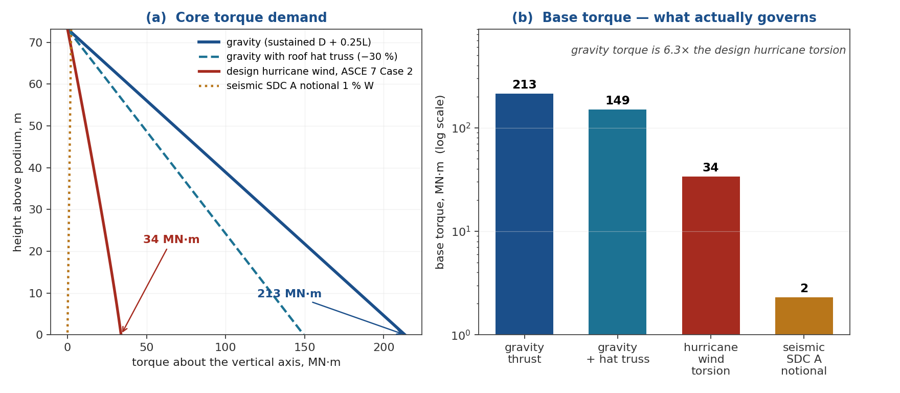
Figure 4. Torque about the vertical axis. The permanent gravity-induced torque dominates the design hurricane torsion by a factor of six, and the SDC A seismic requirement by a factor of ninety.
Two design moves in the built towers follow from this. The first is the roof hat truss, a set of girders cantilevered from each core and connected to all the columns. It suspends part of the upper superimposed load directly into the core as a vertical force, so that load never enters a raked column and never generates a $\tan\theta$ thrust. Published accounts put the reduction in core torsion at about 30 percent, which is the dashed curve in Figure 4(a).
The second is the core itself. Conventionally reinforced walls would reportedly have needed to be six feet thick to take the combined self-weight and hurricane shear. Instead a composite wall was used, with internal steel plates up to 3.75 inches thick and rolled sections in the boundary zones, bringing the wall down to 30 inches. On a residential tower where the core is the least saleable square footage in the building, that difference is the difference between a viable project and an unbuilt one.
Why the Core Detailing Is Everything
A closed thin-walled box is stiff in torsion. Slit it and it collapses. For a rectangular core of enclosed area $A_m$ and wall perimeter $s$, the closed-section torsion constant is the Bredt result
$$J_{closed} = \frac{4A_m^2}{\oint ds/t}$$
while for an open section it drops to the thin-strip value
$$J_{open} = \frac{1}{3}\sum s\,t^3$$
For the 12 m by 8 m core in Table 1 with 0.76 m walls, those are 700 m4 and 5.9 m4. A ratio of 120 to 1. And a building core is slit, at every single floor, by the elevator and stair door openings.
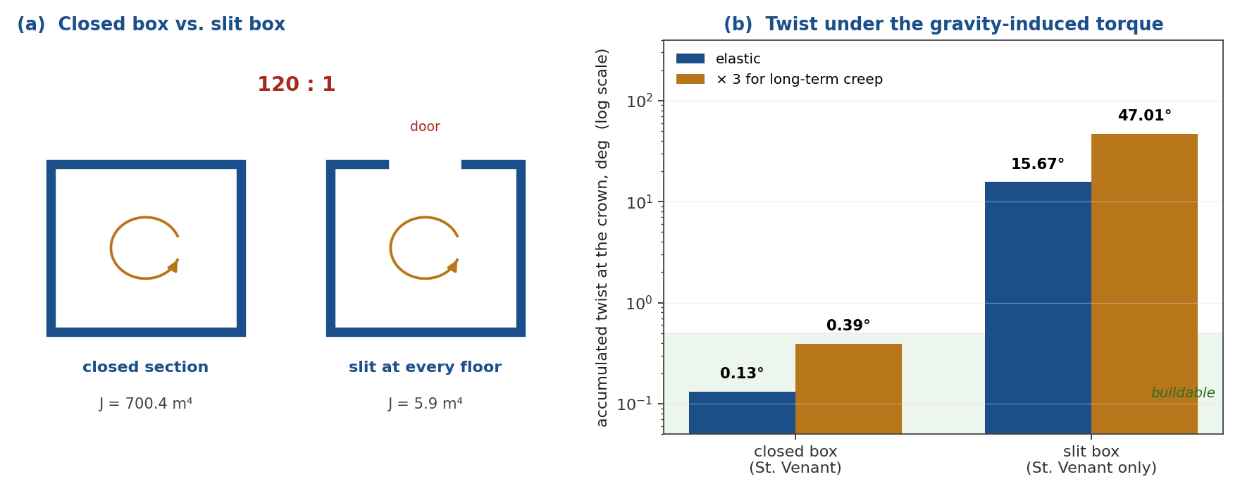
Figure 5. Torsional stiffness of the core. The slit values are a lower bound assuming pure St. Venant action, and they are the reason a twisting tower cannot be built without stiff coupling across the openings.
Integrating the triangular torque profile with cracked stiffness at $0.35EI$ gives 0.13 degrees of accumulated twist at the crown for the closed section, roughly 0.39 degrees once you multiply by three for long-term creep. That is about 100 mm of tangential movement at $r$ = 15 m, which the curtain wall has to absorb. Run the same calculation with pure St. Venant action on the slit section and you get 15.7 degrees, which is nonsense as a physical answer but exactly the point: a twisting tower cannot be built on St. Venant torsion alone. The load is carried by warping, meaning differential axial force in the wall piers, plus shear across the coupling beams that close the openings.
Size those coupling beams. The shear flow around the closed section under 213 MN-m is $q = T/(2A_m)$ = 1112 kN/m, a modest 1.46 MPa (212 psi) in a 0.76 m wall. But across a 2.4 m door opening that shear flow has to pass through one link beam, which means roughly 2670 kN, or 600 kips, at every floor. Permanently. Not a seismic event with ductility credit and cyclic redistribution, but a sustained service load. Steel-plate composite link beams stop looking exotic and start looking mandatory.
One more consequence: because the torque is permanent, the twist creeps. The built towers were cast with a rotational camber, pre-rotated by the predicted elastic plus time-dependent response so the geometry lands where the architect drew it. This is a staged-construction analysis with a creep and shrinkage model, not a code check, and it has to be right before the first slab is poured.
Irregularity in the ASCE 7 Sense
Classify the geometry against ASCE 7 Tables 12.3-1 and 12.3-2 and the picture is more interesting than a simple list of penalties.
| Irregularity | Applies? | Comment |
|---|---|---|
| Horizontal Type 5, nonparallel systems | Yes | Every frame line rotates with height. There are no consistent orthogonal axes anywhere in the tower. |
| Horizontal Type 1a / 1b, torsional | Likely | The centre of mass migrates in plan as the plate rotates and grows while the core stays put, so eccentricity increases with height. |
| Vertical Type 4, in-plane discontinuity | No | The raked columns are gravity members. The lateral system is the core, and the core is continuous and plumb. |
| Vertical Type 3, geometric | No | Plan dimensions of the lateral system do not change story to story. |
Table 2. Code irregularity classification. The lateral-force-resisting system is regular; all of the geometric irregularity lives in the gravity system.
That last point is the design idea, stated in code language. The sculptural geometry was deliberately decoupled from the lateral system. The core is a plain vertical box that a first-year engineer could classify. The price of the decoupling is paid in the diaphragms and the coupling beams, as a permanent gravity demand, rather than in a complicated lateral model.
The Seismic Case, and Why It Is Free Here
Miami-Dade County sits at roughly $S_S$ = 0.05 g and $S_1$ = 0.02 g. That is Seismic Design Category A. In SDC A, the irregularity provisions of ASCE 7 Section 12.3.2 do not apply. Neither does the redundancy factor $\rho$, nor the torsional amplification factor $A_x$, nor the orthogonal combination requirement that Type 5 horizontal irregularity would otherwise trigger. What remains is Section 11.7: structural integrity ties, and the Section 1.4.2 notional lateral force of 1 percent of the dead load at each level.
For the model tower that is 76 kN per level, 1.53 MN of notional base shear, about 15 percent of the wind base shear, and a notional torsion of roughly 2 MN-m, which is 1 percent of the gravity torque. It disappears into the noise.
Overturning is also a non-event. The aspect ratio is $H/B$ = 2.4, which is stocky. The restoring moment from 161 MN of sustained gravity acting at 15 m is 2415 MN-m against a wind overturning moment of 403 MN-m, a demand-capacity ratio of 0.17. Nothing about these towers is close to tipping. The problem was never stability. It was torsion.
Wind, and What the Twist Actually Buys
Chapter 27 of ASCE 7 has no legitimate pressure coefficients for a plan that rotates continuously with height, and none at all for two such towers standing close together with deep cantilevered balcony ledges. This is a Chapter 31 wind tunnel job, with the surrounding built environment modeled. The proximity effect matters at least as much as the shape: for some azimuths one tower sits in the wake of the other and eats its buffeting, and the gap between them channels flow. The ASCE 7 torsional load cases, which apply a fixed eccentricity of $0.15B$, are not meaningful when the eccentricity itself grows with height.
It is common to hear that twisting a tower is an aerodynamic move, and in general it is. Rotating the section decorrelates vortex shedding phase along the height, so the across-wind generalized force loses spanwise coherence. Shanghai Tower and Burj Khalifa both work this way. But it is worth checking whether it does anything here. Take the Strouhal number for a square section, $St$ = 0.11, and a first mode near 1 Hz. The critical velocity for lock-in is
$$U_{crit} = \frac{f_1 B}{St} = \frac{1.0 \times 30}{0.11} = 273 \ \mathrm{m/s}$$
against a design mean hourly speed at roof height of about 49 m/s. The reduced velocity $U/(f_1 B)$ is 1.65, nowhere near the value of seven to ten where lock-in lives. A 240 ft tower with a 30-inch composite core is far too stiff and far too stocky to care. The twist bought views and terraces. It did not buy aerodynamics, and no damper was needed.
Where the geometry does cost money is the envelope. Miami-Dade and Broward are the High Velocity Hurricane Zone, and every glazed assembly needs a Notice of Acceptance based on the TAS protocols. On a tower where no two floor plates are alike, every panel is a one-off in a different pressure zone.
| Protocol | What it is | Analogy |
|---|---|---|
| TAS 201 | Large and small missile impact | A pyroshock or drop test. Single event, pass or fail. |
| TAS 202 | Uniform static air pressure | A static proof load. |
| TAS 203 | Cyclic wind pressure loading, 9000 cycles in positive and negative blocks at fractions of design pressure | A low cycle fatigue qualification test, closer in spirit to a shaker qual than to a proof test. |
Table 3. HVHZ envelope qualification. TAS 203 is the one that should interest anyone who does vibration fatigue.
Hurricane Irma passed on 10 September 2017, less than a year after completion. Reported conditions at the site were on the order of 100 mph winds and a four foot storm surge, and the developer reported that both structures, including the impact glazing, came through well. That is roughly 60 percent of the design wind speed. A useful serviceability data point, not a proof of the 700-year event.
Irregularity in the Random Vibration Sense
Now the other meaning of the word. For a stationary Gaussian response with spectral moments $m_k$, the irregularity factor is
$$\gamma = \frac{n_0}{n_p} = \frac{m_2}{\sqrt{m_0\,m_4}}$$
where $n_0 = \sqrt{m_2/m_0}$ is the zero upcrossing rate and $n_p = \sqrt{m_4/m_2}$ is the peak rate. When $\gamma \to 1$ the process is narrowband, peaks are Rayleigh distributed, and the classical narrowband fatigue estimate is exact. When $\gamma$ falls, small intermediate peaks appear that do not close a rainflow cycle, and the narrowband estimate becomes conservative, sometimes wildly so.
I ran three wind response processes for the model tower: an across-wind lock-in case for a slender prism, the along-wind response of this stiff stocky tower, and a local cladding pressure with no resonance at all. Each was normalized to unit variance, synthesized for one hour at 200 samples per second, rainflow counted, and compared against the narrowband and Dirlik estimates.
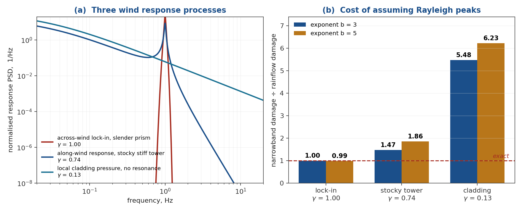
Figure 6. Irregularity factor for three wind response processes, and the resulting error in the narrowband damage estimate.
| Process | $\gamma$ | Cycles per hour | NB / rainflow, b = 3 | NB / rainflow, b = 5 | Dirlik / rainflow, b = 5 |
|---|---|---|---|---|---|
| Across-wind lock-in, slender prism | 1.00 | 3606 | 1.00 | 0.99 | 0.99 |
| Along-wind, stocky stiff tower | 0.74 | 3570 | 1.47 | 1.86 | 0.84 |
| Local cladding pressure, no resonance | 0.13 | 45278 | 5.48 | 6.23 | 1.15 |
Table 4. One hour of synthesized response per case, unit variance, rainflow counted. NB is the classical narrowband estimate $D = n_0 (\sqrt{2}\sigma)^b \Gamma(1+b/2)$.
The lock-in case validates the method: narrowband and rainflow agree to within one percent, as theory requires. The global response of the stocky tower runs at $\gamma$ = 0.74, because 45 percent of its variance is background rather than resonant, and there the narrowband estimate overstates damage by 47 percent at $b$ = 3 and 86 percent at $b$ = 5. The cladding pressure is the eye-opener. With essentially no resonant amplification, $\gamma$ = 0.13, there are 45,000 counted cycles per hour instead of 3,600, and the narrowband estimate is off by a factor of five to six. Dirlik holds within 15 percent across all three.
A Result I Did Not Expect
My first instinct was that twisting the tower should lower $\gamma$, on the reasoning that decorrelating the shedding broadens the force spectrum and therefore broadens the response. So I swept the forcing bandwidth on a lightly damped oscillator to see how much. The answer is: almost none. Widening the force spectrum by a factor of sixty, from $\sigma_f/f_1$ = 0.05 to 3.0, moved $\gamma$ from 0.999 to 0.957. A lightly damped structure narrowbands whatever you feed it.
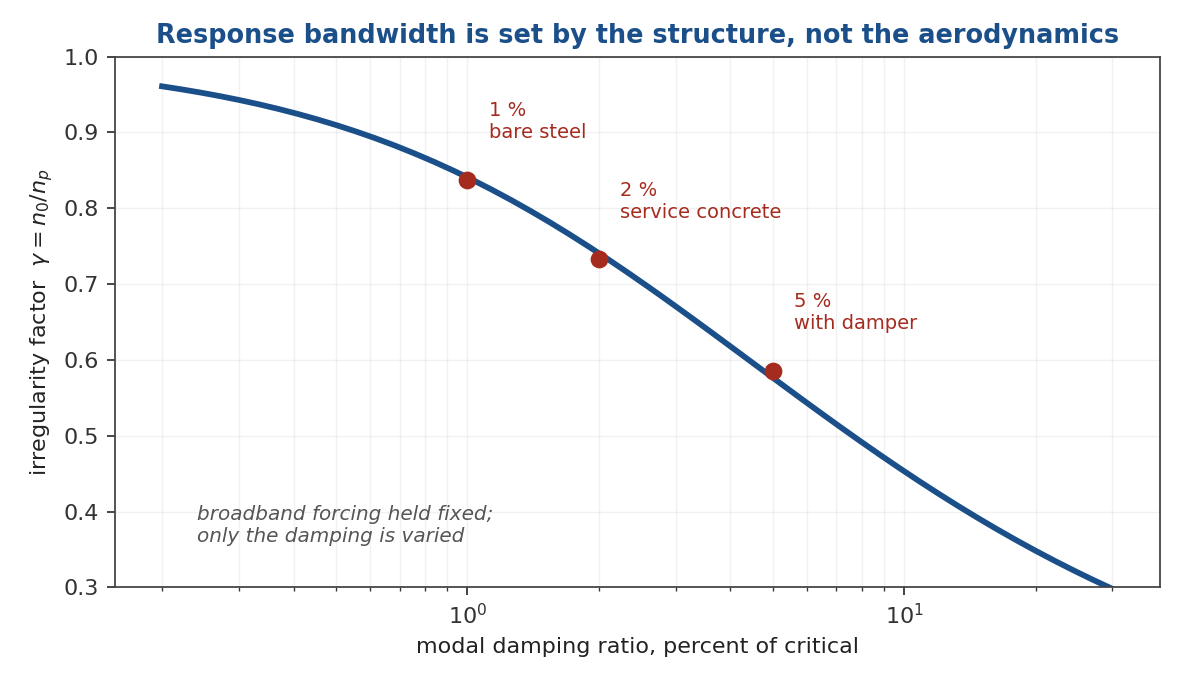
Figure 7. Irregularity factor of the response versus damping, with the forcing held fixed. The structure sets the bandwidth, not the excitation.
Damping is what moves $\gamma$. Holding the broadband buffeting force fixed and varying only the damping ratio takes $\gamma$ from 0.91 at 0.5 percent to 0.73 at 2 percent to 0.39 at 15 percent. So the honest statement about aerodynamic modification is that twisting a tower reduces the magnitude of the coherent across-wind force, not the bandwidth of the resonant response. If you are near resonance, $\gamma$ is close to one no matter what the wind is doing, and a narrowband fatigue estimate is fine. The moment the response stops being resonance-dominated, which is the normal condition for cladding, connections, guardrail anchorages and anything else with no mode in the excitation band, $\gamma$ collapses and so does the narrowband assumption.
What Transfers
Very few of us will design a twisting tower. Several of the lessons show up in ordinary work.
- Any inclined gravity member puts a permanent horizontal force into whatever restrains it. That is true of a raked column, a sloped strut on a skid, a canted equipment leg, or a shaker isolator installed out of plumb. Check where $P\tan\theta$ goes before you check anything else.
- When the geometry has a consistent rotational sense, the individual thrusts cancel as a force and add as a torque. A force check will show nothing wrong.
- Sustained loads creep. A demand that is permanent gets no ductility credit, no cyclic redistribution, and a long-term stiffness that may be a third of the elastic value. Design it at service, not at ultimate.
- Torsion in a thin-walled section is a detailing problem, not a sizing problem. Closed versus slit is two orders of magnitude, and the openings you have to put in are what decide the answer.
- Check the irregularity factor before assuming Rayleigh peaks. If $\gamma$ is above about 0.9, narrowband is fine. Below 0.5 it can be off by a factor of five, and Dirlik costs you almost nothing to run.
- The irregularity factor of a response is set by the structure’s damping and by the split between background and resonant contribution, not by the bandwidth of the input. Do not assume a broadband input gives you a broadband response.
References and Related Reading
- DeSimone Consulting Engineers, project description for Grove at Grand Bay, and the associated STRUCTURE magazine and CRSI case studies.
- V. J. DeSimone et al., Structural Challenges of Twisting Towers, Council on Tall Buildings and Urban Habitat.
- Engineering News-Record, coverage of the twisting geometry and construction, 2015; Architectural Record, post-Irma assessment, 2017.
- ASCE 7, Chapters 11, 12, 26 through 31; Florida Building Code HVHZ provisions and Miami-Dade TAS 201, 202, 203.
- T. Dirlik, Application of Computers in Fatigue Analysis, University of Warwick, 1985.
- Related post: Nastran SOL 111 versus SOL 112 for random vibration fatigue, which covers the same narrowband and Dirlik comparison for an SDOF under broadband base input.
- Free ebooks on shock and vibration response spectra, stress-velocity, fatigue and related topics: Tom’s ebooks.
The worked example in this post uses a generic model built to represent this class of building. It is not the design of any specific structure, and the numbers should be read as order-of-magnitude illustrations of the mechanics rather than as reported design values.