What Solar Trackers Do
A solar tracker is a motorized mounting system that rotates photovoltaic (PV) modules to follow the sun across the sky, keeping the panel surface more nearly perpendicular to the incoming sunlight than a fixed-tilt rack can. The payoff is energy yield: a horizontal single-axis tracker, which rotates east to west about a north-south axis through the day, typically increases annual energy production by roughly 15 to 25% over fixed-tilt mounting at the same site, with the largest gains at low latitudes and in clear-sky climates. Dual-axis trackers, which also follow the sun’s elevation, add a further increment but at greater mechanical complexity, and are mostly confined to concentrating systems that require precise pointing.
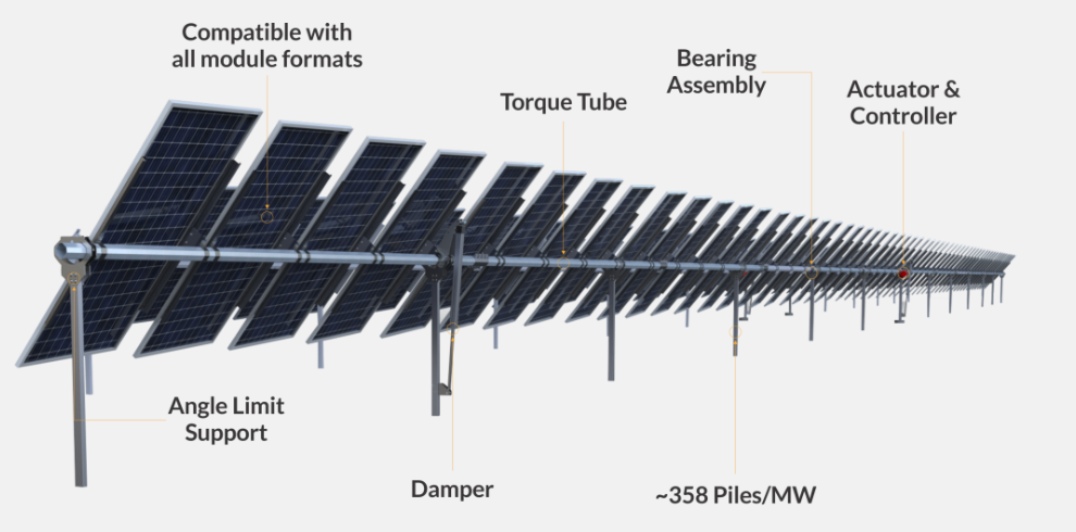
The horizontal single-axis tracker has become the default architecture for utility-scale solar in the Americas, Australia, the Middle East, and much of Asia — the majority of new large-plant capacity in the United States is now built on them. A typical installation is a field of parallel rows, each row consisting of a steel torque tube on driven piles, a slew drive or linear actuator at one or a few points along its length, and dozens of modules clamped along the tube. The same rotation capability that earns the energy gain also serves a protective function: on a wind or hail warning, the controller drives the rows to a defensive stow angle. It is this mechanically simple but structurally slender architecture — a long, flexible, flat plate free to rotate about its own axis in the wind — that sets up the aeroelastic problem examined in this post.
The Aeroelastic Problem
Single-axis solar trackers are among the most torsionally flexible structures in modern civil-mechanical engineering. A typical utility-scale tracker row is a long slender torque tube, 50 to 120 meters in length, carrying a wide flat plate of PV modules, supported on widely spaced posts, and driven at only one or a few points. The result is a system with low torsional stiffness, low rotary inertia per unit length, structural damping on the order of 1 to 2% of critical, and torsional natural frequencies often below 2 Hz. That combination makes trackers susceptible to a classic aeroelastic instability: torsional galloping. Several utility-scale plants have suffered rows twisted apart in windstorms at speeds well below their static design wind speed, and the industry has learned the same lesson that bridge engineers learned at Tacoma Narrows in 1940 — static wind load checks alone do not guarantee dynamic stability.
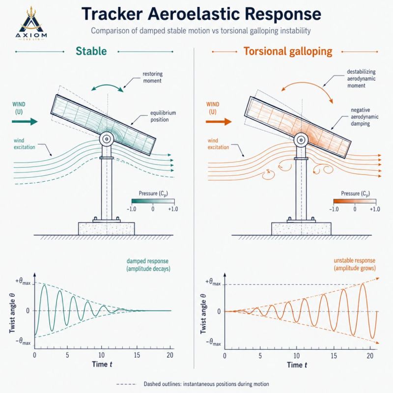
The figure above contrasts the two regimes. On the left, a wind gust twists the panel away from equilibrium, but the aerodynamic and structural moments act as a net restoring, energy-dissipating system. The twist angle $\theta(t)$ oscillates at the torsional natural frequency inside a decaying exponential envelope. On the right, the same geometry at a different tilt angle and wind speed experiences a destabilizing aerodynamic moment. The airflow feeds energy into the torsional mode faster than the structure can dissipate it. The response grows exponentially, limited only by stall, structural yielding, or failure of the drive, dampers, or module clamps.
Equation of Motion
Model the tracker row as a single torsional degree of freedom about the torque tube axis, with mass moment of inertia $J_\theta$, structural damping coefficient $c_\theta$, and torsional stiffness $k_\theta$ (drive plus tube):
The aerodynamic moment per the quasi-steady approximation, for a panel of chord $c = 2b$ and row length $L$ in wind speed $U$, is
where $C_M$ is the moment coefficient about the pivot and $\alpha_{\mathrm{eff}}$ is the effective angle of attack. The key physics is that a twisting panel changes its own angle of attack. When the panel rotates with angular velocity $\dot{\theta}$, the relative wind seen at a reference point offset $b_r$ from the pivot is rotated by approximately $\dot{\theta} \, b_r / U$. Linearizing about the equilibrium tilt angle:
Moving the aerodynamic terms to the left side of the equation of motion gives effective stiffness and damping coefficients:
Two distinct instabilities fall out of these expressions.
Torsional divergence is a static (non-oscillatory) instability. If $dC_M/d\alpha > 0$, the aerodynamic moment gradient opposes the structural spring, and $k_{\mathrm{eff}}$ vanishes at a divergence speed that scales with $\sqrt{k_\theta}$. The panel simply twists over.
Torsional galloping is the dynamic instability shown in the figure. The rate-dependent term acts as aerodynamic damping. Depending on the sign of the moment slope at the operating tilt angle, this term either adds to or subtracts from the structural damping. When the aerodynamic contribution is negative and its magnitude exceeds $c_\theta$, the total damping is negative and every oscillation cycle extracts net energy from the wind. Since the destabilizing term grows linearly with $U$ while structural damping is fixed, there is a critical onset speed above which the response envelope grows without bound.
Key point: Torsional galloping is a self-excited, negative-damping instability, not a resonance. The wind does not need to contain energy at the natural frequency, and the onset is governed by an energy balance: instability begins at the wind speed where negative aerodynamic damping exactly cancels structural damping. Because structural damping in a tracker row is only 1–2% of critical, the margin is thin. Above onset, amplitude grows exponentially in a matter of cycles — at a 1 Hz torsional frequency, a row can go from benign buffeting to destructive twist in well under a minute.
Why Trackers Are Vulnerable
A flat plate at low incidence is aerodynamically unforgiving. Near 0° tilt, flow separates alternately from the leading edge, the center of pressure wanders across the chord, and the moment coefficient slope can be strongly destabilizing. Combine that airfoil-like sensitivity with the structural characteristics of a long tracker row and the ingredients for instability are all present:
| Factor | Effect on Stability |
|---|---|
| Long torque tube, single drive point | Low torsional stiffness; row ends can twist several degrees relative to the drive; low natural frequency |
| Bolted steel construction, few joints working | Structural damping typically 1–2% of critical — little energy dissipation to offset aerodynamic input |
| Wide flat-plate planform | Large chord $c$ enters the destabilizing terms as $c^2$ and $c^3$; strong moment sensitivity near flat tilt |
| Shallow stow angle (near 0°) | Historically chosen to minimize static load, but places the panel in the tilt range where the moment slope is most destabilizing |
| Exposed first rows of an array | Interior rows are sheltered; perimeter rows see the full onset flow and typically fail first |
Wind tunnel studies published after early field failures showed that the traditional flat stow at 0° tilt — intuitive for minimizing static drag and lift — can be the least stable configuration against torsional galloping.
Mitigation Measures
Every practical fix attacks one of the three parameters in the stability equations: the structural damping $c_\theta$, the torsional stiffness $k_\theta$, or the aerodynamic moment slope $dC_M/d\alpha$ at the operating condition. Framing mitigation this way makes clear which instability each measure addresses and why measures can be stacked.
| Measure | Parameter Attacked | Effect |
|---|---|---|
| High-tilt stow (roughly 30° to 60°) | $dC_M/d\alpha$ | Places the panel in fully separated flow where the moment slope is benign; aerodynamic damping becomes positive or only weakly negative |
| Supplemental viscous or friction dampers along the row | $c_\theta$ | Raises the galloping onset speed directly; onset occurs where negative aerodynamic damping cancels total structural damping, so added damping buys speed margin |
| Multi-drive architecture (distributed drive points) | $k_\theta$ | Raises the torsional frequency and divergence speed; reduces twist amplification at the row ends relative to the drive |
| Larger-diameter or thicker-wall torque tube; stiffer drive gearbox | $k_\theta$ | Same benefits as above at the cost of steel; also reduces static twist under gravity and unbalanced snow load |
| Shorter rows | $k_\theta$, $L$ | Stiffer per unit length and less exposed area feeding energy into the mode |
| Fast wind-triggered stow with backup power | Operational | Ensures the array reaches the stable stow angle before onset conditions arrive; the stability margin at the stow angle is only useful if the array can get there |
Note the different scaling of the two instabilities: the destabilizing damping term grows linearly with $U$, while the destabilizing stiffness term grows with $U^2$. Added damping is therefore effective against galloping but does nothing for divergence, which can only be addressed through stiffness or the moment slope. A robust design typically stacks a high-tilt stow strategy with supplemental dampers, so that a single failed element does not eliminate the margin.
Historical aside: The Tacoma Narrows Bridge failure of November 1940 was a torsional aeroelastic instability of the same family — a bluff flexible structure with negative aerodynamic damping in twist, not simple vortex-shedding resonance as often claimed. The deck oscillated torsionally at about 0.2 Hz with growing amplitude in a steady 42 mph wind. The tracker industry effectively rediscovered this mechanism eight decades later at a smaller scale.
Design and Test Implications
Static wind load calculations per building-code pressure coefficients are necessary but not sufficient for trackers. A defensible design basis includes:
1. Aeroelastic wind tunnel testing of a dynamically scaled tracker model, matching reduced velocity $U/(f_\theta c)$, inertia, and damping — rigid pressure-tap models cannot reveal galloping onset.
2. Measurement of the torsional natural frequency and damping ratio of the as-built row, since $c_\theta$ and $k_\theta$ in the stability equations are structural properties, not aerodynamic ones. A simple pluck or snap-back test with an accelerometer at the row end, processed with a log-decrement or half-power calculation, is sufficient.
3. Verification that the stow controller can reach the stable stow angle within the warning time available from the site anemometry, including under loss-of-power conditions.
4. Periodic re-verification of damper condition. A seized or leaking damper silently erodes the stability margin while the array continues to operate normally in calm weather.
The twist-angle time histories in the figure are exactly what such a field test produces: a decaying sinusoid confirms positive total damping at the test condition, and the log-decrement of the envelope quantifies the margin. Any tendency of the envelope to flatten or grow as wind speed increases is the signature of approaching onset.
Related Vibrationdata Posts
South Dakota Wind Turbine Collapse — wind loading and IEC 61400-1
Wind Turbine Blade Design Trade-offs
DTW McNamara Terminal Arched Roof — wind and snow structural dynamics
References
C. Rohr, P. Bourke & D. Banks, Torsional Instability of Single-Axis Solar Tracking Systems, 14th International Conference on Wind Engineering, Porto Alegre, 2015.
R. Blevins, Flow-Induced Vibration, 2nd ed., Krieger, 2001.
J.P. Den Hartog, Mechanical Vibrations, 4th ed., McGraw-Hill, 1956.
J.D. Holmes, Wind Loading of Structures, 3rd ed., CRC Press, 2015.
T. Irvine, Vibrationdata publications & free ebooks: https://blog.vibrationdata.com/2025/11/27/toms-ebooks/