Introduction
Nearly every utility-scale wind turbine built today has three blades. This was not inevitable. One-blade and two-blade machines were built and fielded in the 1980s and 1990s, and multi-blade rotors dominated the farm windmill era for a century. The three-blade configuration won a genuine engineering competition, and the reasons touch nearly every discipline: aerodynamics, structural dynamics, acoustics, fatigue, economics, and even psychology.
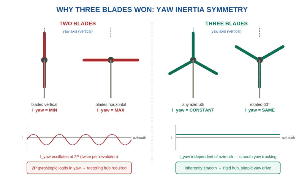
Azimuth, in the wind turbine context, is the rotor’s rotation angle — where the blades are in their spin cycle at a given instant, measured about the shaft axis.
The convention is to track a single reference blade. Azimuth ψ = 0° typically means that blade is pointing straight up (12 o’clock). As the rotor turns, ψ sweeps from 0° to 360° and repeats every revolution. So “blades vertical” on a two-blade rotor means ψ = 0° or 180°, and “blades horizontal” means ψ = 90° or 270°.
In my diagram, the horizontal axis of the two small inertia traces is this angle. The two-blade rotor’s yaw inertia peaks twice per revolution (at 90° and 270°) and bottoms out twice (at 0° and 180°) — that’s why the fluctuation is “2P,” twice per rev.
The three-blade rotor’s inertia is the same at every ψ, hence the flat line.
This post walks through the trade study. As usual on this blog, the structural dynamics angle gets special attention, because the deepest reason three blades won is a dynamics reason that rarely makes it into popular explanations.
The Baseline Physics
A wind turbine extracts kinetic energy from the air stream passing through its rotor disk. The theoretical ceiling is the Betz limit:
$$C_{P,max} = \frac{16}{27} \approx 0.593$$No rotor, regardless of blade count, can capture more than 59.3% of the wind’s kinetic energy. Modern three-blade machines achieve $C_P \approx$ 0.45 to 0.50 at their design point — remarkably close to the ceiling.
The key operating parameter is the tip speed ratio:
$$\lambda = \frac{\Omega R}{V}$$where $\Omega$ is the rotor angular speed, $R$ is the rotor radius, and $V$ is the wind speed. Each blade count has an optimum $\lambda$. Fewer blades must spin faster to sweep the same air; more blades can turn slowly. Roughly:
| Blade Count | Optimum Tip Speed Ratio | Character |
|---|---|---|
| 1 | ~11 or higher | Very fast, counterweight required |
| 2 | ~9 to 10 | Fast, light, dynamically troubled |
| 3 | ~7 | The modern standard |
| Many (15 to 20) | ~1 | High torque, low speed: the farm water pumper |
Aerodynamic Efficiency
Adding blades increases peak $C_P$, but with sharply diminishing returns. Going from two to three adds roughly 2 to 3%. Going from three to four adds under 1% while adding a full blade’s worth of cost and mass. Each additional blade also flies in the disturbed wake shed by the ones ahead of it, and tip losses multiply.
At the other extreme, the classic multi-blade farm windmill is aerodynamically inefficient ($C_P \approx$ 0.15 to 0.30) but produces high starting torque at low speed — exactly what a reciprocating well pump needs. Blade count is always matched to the job.
The Structural Dynamics Story — Why Two Blades Lost
On paper the two-blade rotor looks attractive: one fewer blade to buy, a lighter hub, and simpler logistics (the rotor can be assembled on the ground as a single unit and lifted flat). Several serious machines were built this way. What killed the configuration was yaw dynamics.
The rotating inertia problem
Consider the rotor’s mass moment of inertia about the yaw (vertical) axis. For a three-blade rotor, the polar symmetry makes this inertia independent of azimuth angle — the rotor presents the same inertia to a yaw motion no matter where the blades happen to be in their rotation. The yaw drive sees a smooth, constant load.
A two-blade rotor has no such symmetry. When the blades are vertical, the rotor’s inertia about the yaw axis is minimal; when horizontal, it is maximal. The inertia oscillates at twice the rotor speed (2P). Every time the nacelle yaws to track the wind while the rotor spins, this fluctuating inertia generates a large oscillating gyroscopic moment that hammers the yaw drive, the mainframe, and the tower top at 2P.
Two-blade designers fought back with the teetering hub — a hinge that lets the rotor rock a few degrees out of plane, decoupling the blade flapping moments from the shaft. Teetering works in steady conditions but adds complexity, and in extreme gusts or yaw errors the teeter motion can hit its end stops, producing impact loads worse than the problem it solved.
Excitation harmonics
Every rotor excites the tower at the blade passing frequency and its harmonics:
$$f_{BP} = N \, \Omega / (2\pi)$$where $N$ is the blade count. Each blade passage past the tower (tower shadow) and each traverse of the atmospheric shear gradient delivers a load pulse. A three-blade machine loads the tower at 3P with smaller per-blade pulses; a two-blade machine delivers larger pulses at 2P, closer to typical tower fundamental frequencies for soft-stiff designs. Placement of the tower natural frequency between 1P and NP bands is a fundamental design constraint, and the 3P machine gives the designer more room.
The dynamics bottom line. The three-blade rotor is the minimum blade count that yields an azimuth-independent rotor inertia. It is the cheapest configuration that is inherently smooth in yaw. That single property, more than aerodynamics, is why three blades conquered the industry.
Noise
Aerodynamic noise from a rotor blade rises steeply with tip speed. The commonly used scaling for trailing-edge broadband noise is approximately:
$$L_W \propto V_{tip}^{5}$$A fifth-power law is brutal. Because a two-blade rotor runs at $\lambda \approx$ 9 to 10 versus $\approx$ 7 for three blades, its tip speed is roughly 30 to 40% higher at the same wind speed, which translates to several decibels of additional source noise. For land-based turbines sited near residences, where sound power limits are often the binding constraint on operation, the quieter three-blade machine wins again.
Offshore, noise limits relax, which is why two-blade concepts periodically resurface for offshore application — higher tip speed becomes an advantage there, allowing a lighter, faster, cheaper drivetrain.
Cost and Mass
Blades represent roughly 15 to 25% of turbine capital cost. The trade is not simply “one fewer blade saves money”:
- A two-blade rotor must run faster and each blade carries more load, so each blade is heavier and more expensive than one blade of an equivalent three-blade set.
- The teetering hub adds cost and maintenance that a rigid three-blade hub avoids.
- The faster two-blade rotor permits a lighter, cheaper gearbox (torque scales inversely with speed for constant power) — a genuine saving.
- Transport and erection favor two blades: fewer road convoys per rotor, and single-lift rotor installation.
Net capital cost differences historically came out to a few percent — not decisive either way. The lifecycle costs of the dynamics problems were decisive.
Fatigue and Maintenance
A wind turbine blade experiences on the order of $10^8$ gravity-driven edgewise load cycles over a 20-year life — every revolution reverses the gravity moment on the blade root. This is among the most severe fatigue environments of any civil machine, and it applies per blade regardless of count.
- More blades: more pitch bearings, more pitch actuators, more lightning protection paths, more root connections — more items on the maintenance schedule.
- Fewer blades: higher loads per blade, teeter hardware (for two-blade machines) subject to wear and impact damage, and higher tip speeds that accelerate leading-edge erosion from rain and particulates. Leading-edge erosion is strongly tip-speed dependent, and it is one of today’s dominant blade maintenance issues even at three-blade tip speeds.
The Aesthetic Footnote
It is often reported that public acceptance played a role in the three-blade victory, and there is substance to it. A spinning two-blade rotor appears to pulse or lope to the eye — a consequence of the same azimuth-dependent inertia asymmetry discussed above, expressed visually. The three-blade rotor reads as smooth and calm. In an industry that requires public permission to site machines near communities, this mattered.
Summary Table
| Attribute | 2 Blades | 3 Blades | Advantage |
|---|---|---|---|
| Peak aerodynamic efficiency | ~2 to 3% lower | Baseline | 3 |
| Yaw dynamics | 2P gyroscopic loads, teeter hub needed | Azimuth-independent inertia, smooth | 3, decisively |
| Noise | Higher (tip speed, $V^5$ law) | Lower | 3 |
| Rotor capital cost | Slightly lower | Slightly higher | 2, marginally |
| Drivetrain cost | Lower (faster shaft, less torque) | Higher | 2 |
| Transport & erection | Simpler, single-lift rotor | More lifts or larger crane time | 2 |
| Maintenance | Teeter wear, erosion at high tip speed | One more pitch system | Roughly even |
| Public acceptance | Visually loping | Visually smooth | 3 |
Closing Observations
The three-blade rotor is a compromise that wins on the criteria that matter most on land: smooth yaw dynamics without a teetering hub, tower excitation pushed up to 3P with smaller pulses, several decibels of noise margin from lower tip speed, and near-ceiling aerodynamic efficiency. The two-blade machine survives as a niche concept for offshore sites where its noise penalty is irrelevant and its installation advantages are amplified by marine logistics.
The lesson generalizes: blade count is not an aerodynamic decision with structural consequences — it is a structural dynamics decision with aerodynamic consequences. The inertia symmetry of the three-blade rotor is the quiet hero of the modern wind industry.
📌 Further Reading: This article is part of our Wind Turbine Vibration & Dynamics Engineering Guide. Visit the hub page for more case studies and analysis on turbine fatigue and rotor mechanics.
— Tom Irvine, VibrationData