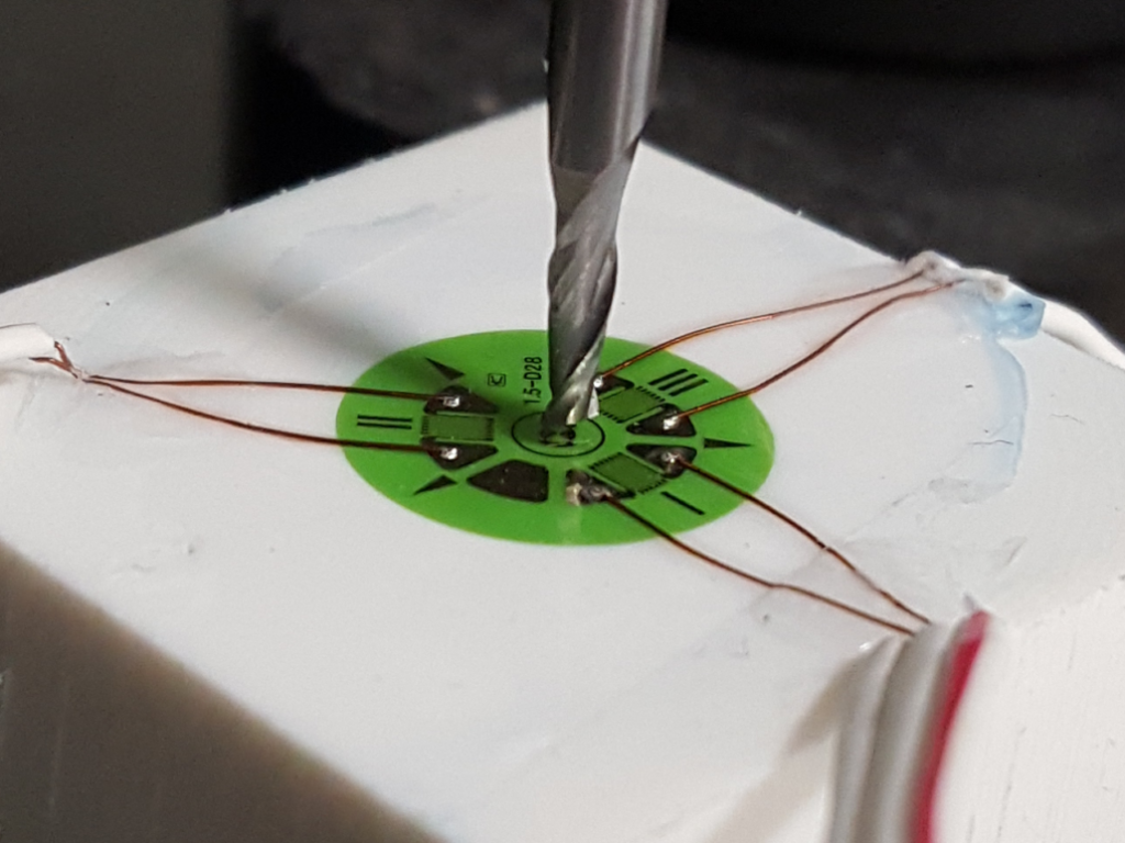
Image credit: https://www.sintechnology.com/portfolio-articoli/hole-drilling/
Drilling a hole into a structure is normally something an engineer tries to avoid — holes are stress concentrators, fatigue initiation sites, and sources of structural weakness. But in one important application, drilling a small hole is precisely how engineers measure the stress state that already exists in a structure. This is the hole-drilling method for residual stress measurement, standardized in ASTM E837.
This post explains the physical basis of the method, the governing equations, practical procedure, limitations, and engineering applications — including its relevance to fatigue life assessment and structural integrity.
What Is Residual Stress?
Residual stresses are self-equilibrating internal stresses present in a component in the absence of any external load. They arise from any manufacturing or service process that introduces non-uniform plastic deformation:
- Welding (thermal gradients during solidification)
- Machining and grinding (surface layer plastic flow)
- Shot peening and cold rolling (deliberate compressive layer introduction)
- Heat treatment and quenching (differential thermal contraction)
- Forming and bending (through-thickness plasticity gradients)
- Press fitting and interference fits (contact zone hoop stresses)
Residual stresses are algebraically superimposed on applied service stresses. Compressive residual stress at a surface is generally beneficial — it reduces the effective mean stress at potential fatigue crack initiation sites. Tensile residual stress is detrimental — it adds to applied tension and can significantly reduce fatigue life or promote stress corrosion cracking.
The stress-velocity relationship \( \sigma = \rho c V \) used in vibration severity assessment gives peak dynamic stress amplitude, but residual stress is an additional, quasi-static component that shifts the mean stress level. Both matter for life assessment.
Physical Basis of the Hole-Drilling Method
The hole-drilling method exploits a simple physical principle: when a small hole is drilled into a stressed material, the material that is removed was carrying load. Removing it allows the surrounding material to partially relax — the elastic strain field near the hole changes. By measuring those strain changes at the surface before and after drilling, the original residual stress state can be back-calculated.
The method was first proposed by Mathar in 1934 and has been refined continuously since. The current authoritative standard is ASTM E837-20, which covers both uniform and non-uniform stress distributions through the thickness.
Experimental Setup
The standard setup consists of three components:
1. Strain Gauge Rosette
A special three-element strain gauge rosette is bonded to the surface at the measurement location. The standard ASTM E837 rosette geometry (Type A or Type B) has three gauges arranged radially around a central point, oriented at 0°, 45°, and 135° (or 0°, 90°, and 135° for the B rosette). Gauge numbering follows a specific convention — gauge 1 at 0°, gauge 2 at 45°, gauge 3 at 90° for the A rosette.
The rosette is sized to the hole diameter. For a standard D = 1.8 mm diameter hole, the gauge grid centers are located at a mean radius \( r_m \approx 2.5 \) mm from the hole center.
2. High-Speed Drill
A tungsten carbide or diamond-coated end mill is used, driven at 20,000–400,000 RPM. High rotational speed is essential to minimize the additional residual stresses introduced by the drilling operation itself — a phenomenon called machining-induced stress. Air-turbine systems are common for this reason; they achieve high RPM with low torque and minimal heat generation.
3. Precision Depth Control
Drilling is performed in incremental depth steps, typically 0.05–0.1 mm per increment, to a total depth of approximately 0.4–0.5 times the hole diameter. Strain readings are recorded after each increment. This incremental approach allows the residual stress profile to be resolved as a function of depth, not just as a through-thickness average.
Governing Equations
For a uniform biaxial stress state (the simplified case), the relieved strains \( \varepsilon_1 \), \( \varepsilon_2 \), \( \varepsilon_3 \) at the three gauge positions are related to the principal residual stresses \( \sigma_{\max} \) and \( \sigma_{\min} \) by:
\[ \varepsilon_1 = \frac{A}{E}(\sigma_{\max} + \sigma_{\min}) + \frac{B}{E}(\sigma_{\max} – \sigma_{\min}) \cos 2\beta \]
\[ \varepsilon_2 = \frac{A}{E}(\sigma_{\max} + \sigma_{\min}) – \frac{B}{E}(\sigma_{\max} – \sigma_{\min}) \]
\[ \varepsilon_3 = \frac{A}{E}(\sigma_{\max} + \sigma_{\min}) + \frac{B}{E}(\sigma_{\max} – \sigma_{\min}) \cos 2\beta’ \]
where \( A \) and \( B \) are dimensionless calibration coefficients that depend on hole geometry (diameter and depth relative to rosette dimensions), \( E \) is Young’s modulus, and \( \beta \) is the angle between gauge 1 and the maximum principal stress direction.
The calibration coefficients \( \bar{a} \) and \( \bar{b} \) (normalized forms of \( A \) and \( B \)) are tabulated in ASTM E837 as a function of normalized hole depth \( z/D \). They account for the three-dimensional stress relief geometry — the hole is not a through-hole, so the Kirsch solution for a circular hole in an infinite plate does not apply directly.
Stress Combination Variables
ASTM E837 defines three intermediate strain combinations from the three gauge readings:
\[ P = \varepsilon_3 + \varepsilon_1 \]
\[ Q = \varepsilon_3 – \varepsilon_1 \]
\[ T = \varepsilon_3 + \varepsilon_1 – 2\varepsilon_2 \]
The maximum and minimum principal stresses are then:
\[ \sigma_{\max}, \sigma_{\min} = \frac{-E}{4\bar{a}} P \pm \frac{E}{4\bar{b}} \sqrt{Q^2 + T^2} \]
And the angle \( \beta \) of the maximum principal stress from gauge 1:
\[ \beta = \frac{1}{2} \arctan\left(\frac{T}{Q}\right) \]
Non-Uniform Stress: The Integral Method
For non-uniform residual stress fields — which occur in welds, case-hardened surfaces, and shot-peened layers — the incremental strain data from each drilling step are processed using the integral method. This treats the residual stress at each depth increment as an unknown and back-calculates the full depth profile by solving a system of equations of the form:
\[ \{\varepsilon\} = [C]\{\sigma\} \]
where \( [C] \) is the calibration coefficient matrix assembled from the \( \bar{a} \) and \( \bar{b} \) values for each depth increment combination, \( \{\sigma\} \) is the vector of unknown stresses at each depth, and \( \{\varepsilon\} \) is the vector of measured relieved strains. The solution requires matrix inversion and is sensitive to measurement noise — Tikhonov regularization is sometimes applied to stabilize the inversion.
Measurement Uncertainty
Several factors contribute to measurement uncertainty in hole-drilling:
- Eccentricity error: If the drilled hole center is offset from the rosette center, a systematic error is introduced. ASTM E837 specifies a maximum allowable eccentricity of 0.004D (approximately 0.007 mm for a standard hole).
- Machining-induced stress: The drilling operation itself plastically deforms a thin layer at the hole surface, introducing spurious compressive stresses. High-speed drilling minimizes but does not eliminate this error.
- Plasticity effects: The method is based on elastic strain relief. If the residual stress exceeds approximately 60–80% of the material yield strength, plastic deformation occurs at the hole edge and the linear elastic back-calculation is no longer valid.
- Surface preparation: Rosette bonding quality, surface roughness, and residual adhesive stresses all contribute to baseline uncertainty.
- Depth measurement: Depth resolution of the drilling increment affects the accuracy of the non-uniform stress profile.
For well-controlled laboratory conditions, ASTM E837 achieves stress uncertainties of approximately ±10–20 MPa. Field measurements on structural welds or in-service components are typically ±20–40 MPa.
Comparison with Other Residual Stress Methods
| Method | Depth range | Destructive? | Spatial resolution | Typical uncertainty |
|---|---|---|---|---|
| Hole drilling (ASTM E837) | 0–1 mm | Semi (small hole) | ~1–2 mm | ±10–40 MPa |
| X-ray diffraction (XRD) | Surface only (~10 µm) | No | ~1 mm | ±10–20 MPa |
| Neutron diffraction | Full thickness | No | ~1–2 mm | ±10–30 MPa |
| Slitting / contour method | Full thickness | Yes (sectioning) | ~0.5 mm | ±5–20 MPa |
| Ultrasonic (EMAT) | Through thickness | No | ~10 mm | ±30–50 MPa |
| Blind hole drilling (deep) | 0–5 mm | Yes | ~3–5 mm | ±20–50 MPa |
Hole drilling occupies a practical middle ground: it is semi-destructive (the small hole can often be tolerated in non-critical locations), portable for field use, and capable of depth profiling — advantages that fully non-destructive methods like XRD (surface only) or ultrasonic (poor spatial resolution) do not simultaneously offer.
Engineering Applications
Weld Qualification
Welded joints in pressure vessels, pipelines, and aerospace structures develop tensile residual stresses in the heat-affected zone (HAZ) that can equal or exceed the material yield strength. Post-weld heat treatment (PWHT) is specified to reduce these stresses, but verification requires measurement. Hole drilling on the weld toe and HAZ before and after PWHT quantifies the stress relief achieved.
Shot Peening and Surface Treatment Verification
Shot peening induces a compressive residual stress layer 0.1–0.5 mm deep, with peak compression of 300–600 MPa in aluminum alloys and 400–900 MPa in steels. This is the primary fatigue life enhancement mechanism in aerospace landing gear, turbine blades, and automotive springs. Hole drilling with incremental depth steps verifies that the required compressive layer depth and magnitude have been achieved after peening.
Fatigue Life Assessment
Residual stress shifts the mean stress \( \sigma_m \) in the Goodman or Smith-Watson-Topper (SWT) damage models. The SWT parameter is:
\[ \sigma_{\max} \varepsilon_a = \frac{(\sigma_f’)^2}{E} (2N_f)^{2b} + \sigma_f’ \varepsilon_f’ (2N_f)^{b+c} \]
where \( \sigma_{\max} = \sigma_m + \sigma_a \) includes the residual stress as part of the mean. A compressive residual stress of −300 MPa in an aluminum alloy can double or triple the predicted fatigue life under the same applied alternating stress amplitude. Hole drilling provides the measured \( \sigma_m^{\text{residual}} \) input to this calculation.
In-Service Structural Assessment
Bridges, offshore platforms, and pressure vessels accumulate residual stresses from fabrication, in-service plastic overloads, and repair welding. Hole drilling at critical locations — weld toes, notch roots, corrosion pits — provides stress state data for fitness-for-service (FFS) assessments per API 579 or BS 7910.
Additive Manufacturing
Metal additive manufacturing (AM) — laser powder bed fusion, directed energy deposition — produces complex residual stress fields due to rapid solidification and thermal cycling. Hole drilling is increasingly used to characterize these fields in AM components before post-process heat treatment, complementing neutron diffraction mapping of the bulk.
Procedure Summary
A standard ASTM E837 hole-drilling measurement follows these steps:
- Select measurement location and prepare the surface (grind, polish, degrease).
- Bond the strain gauge rosette concentrically at the target point. Allow adhesive to cure fully.
- Connect the rosette to a strain indicator and record baseline (zero-load) readings.
- Mount the high-speed drill guide concentrically over the rosette center using the alignment fixture.
- Drill incrementally to the target depth (typically 8–10 increments of 0.05 mm each), recording strain at each increment after settling.
- Measure the final hole diameter and depth using an optical comparator or profilometer.
- Apply ASTM E837 calibration coefficients \( \bar{a} \) and \( \bar{b} \) appropriate to the measured geometry.
- Solve for principal stresses and orientation using the uniform-stress or integral method as appropriate.
The Irony of Drilling to Measure Stress
There is a satisfying irony in the hole-drilling method. In fracture mechanics, a drilled hole reduces the stress concentration at a crack tip — the stop-drilling principle discussed in a companion post on this site. In residual stress measurement, a drilled hole reveals the stress that was already there, hidden inside the material. In both cases, the hole is doing useful engineering work. The difference is whether you are managing a stress field or interrogating one.
The ancient Egyptians drilled holes in the Ramesses II bust to attach lifting ropes. Structural engineers drill holes in welds to measure residual stress. The geometry is the same. The intent is different. The physics connects them.
References
- ASTM E837-20, Standard Test Method for Determining Residual Stresses by the Hole-Drilling Strain-Gage Method, ASTM International.
- Schajer, G.S. (ed.), Practical Residual Stress Measurement Methods, Wiley, 2013.
- Mathar, J., “Determination of Initial Stresses by Measuring the Deformation Around Drilled Holes,” Transactions of the ASME, 1934.
- Vishay Micro-Measurements, Application Note TN-503, Measurement of Residual Stresses by the Hole-Drilling Strain Gage Method.
Tom Irvine is the author of VibrationData and teaches professional courses in structural dynamics, shock, vibration, and acoustics. See vibrationdata.com for course listings and free technical resources.
Looking for a deep dive on this topic? Explore our comprehensive guide and resource collection on the Residual Stress & Structural Integrity Hub.