Image courtesy of: https://martin-baker.com/ejection-seats/
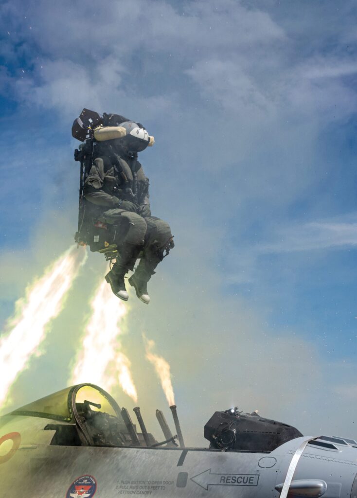
Fatigue Load Environment for Fighter Jet Ejection Seat Metal Components
1. Background
Ejection seats such as the ACES II (F-15, F-16, F-22, B-1, B-2) and Martin-Baker Mk.16 are classified as aircrew automated escape systems under MIL-S-18471G. The seat structure is designed to the same airframe reliability philosophy as the host aircraft: safe-life or damage-tolerance per MIL-A-8866, with a scatter factor of 4.0 applied to material coupon fatigue data.
The seat must function reliably across a service life of 7,500–20,000 flight hours yet survive an ejection event that is complete in under three seconds. Both regimes impose fatigue damage.
2. Quasi-Static Inertial Loads
Normal maneuvering imposes repeated inertial loads on every structural attachment point. Fighter aircraft design envelopes are bounded by:
- Vertical (normal): +9g limit / +13.5g ultimate
- Lateral: ±3g limit
- Longitudinal: ±3g limit (larger for arrested landings and catapult launches)
Structural margins follow the 1.5× factor of safety from Design Limit Load (DLL) to Design Ultimate Load (DUL). The seat structure must carry these loads without yielding at DLL and without fracture at DUL.
The instantaneous stress at a cross-section of area A and section modulus Z is:
where P is the axial force and M is the bending moment derived from the inertial load times the structural offset arm.
Crash Loads (MIL-STD-810H Method 513.8, Procedure III)
| Direction | Acceleration (g) |
|---|---|
| Forward | 20 |
| Aft | 8 |
| Lateral | 8 |
| Upward | 3 |
| Downward | 10–15 |
At these levels the seat is not required to remain undamaged, but must not eject hazardous fragments or block aircrew egress.
Superposition During Ejection
When the aircraft is maneuvering at the time of ejection, the impressed g-field adds directly to the catapult acceleration. A catapult applying 18g at 1g conditions will apply approximately 23g to the seat structure if the aircraft is already pulling 5g. The seat frame must be designed for this vector sum.
3. Sine Vibration
Rotating turbomachinery produces discrete tonal excitation that propagates through the airframe to the seat rails. Sources include:
- N1 (fan/LP spool) and N2 (HP spool) shaft fundamentals and harmonics
- Fan blade passage frequency: BPF = N1 × (fan blade count)
- Turbine blade passage frequencies at higher harmonics
For a typical fighter turbofan at takeoff power, BPF may fall in the range 600–1200 Hz. Sine sweep qualification testing per MIL-STD-810H Method 514.8 covers 5–2000 Hz at 2–10 g peak, with resonance dwell at identified structural modes. Resonance dwell is the primary sine fatigue driver; cumulative cycles at resonance can accumulate rapidly.
4. Random Vibration
Broadband random vibration is the primary steady-state fatigue mechanism during normal carriage. Sources include turbulent boundary layer pressure fluctuations, jet exhaust noise, and acoustic excitation of panels.
The power spectral density (PSD) of the acceleration input at the seat structure is typically characterized as a shaped broadband spectrum from 20 to 2000 Hz. Representative levels for fighter jet internal cockpit structure:
| Frequency Band | PSD Level (g²/Hz) |
|---|---|
| 20–100 Hz | 0.01–0.04 |
| 100–500 Hz | 0.03–0.10 |
| 500–2000 Hz | 0.01–0.04 (rolloff) |
The overall Grms for cockpit structure is typically 5–15 Grms depending on mission phase and proximity to engine mounts.
Fatigue damage under random vibration is computed via the Fatigue Damage Spectrum (FDS):
where ni is the number of stress cycles at amplitude Si and Ni is the allowable cycles from the material S-N curve. Rainflow cycle counting is applied to the stress response time history at each critical location.
Laboratory test duration is compressed by scaling the PSD amplitude upward while preserving total damage, per the MIL-STD-810H Damage Potential method:
where b is the S-N slope exponent (typically 4–8 for metals) and T denotes exposure duration.
5. Gunfire Shock / Sine-on-Random
Gun-armed fighters — F-16 with the M61A2 Vulcan at 6000 rounds/min (100 Hz firing rate), for example — produce a high-rate repetitive shock that is fundamentally different from stationary random vibration.
Per MIL-STD-810H Method 519.8, the gunfire environment is characterized by four single-frequency harmonically related sine peaks superimposed on a broadband random spectrum. The peaks occur at:
For the M61A2: 100, 200, 300, and 400 Hz tones riding on broadband noise. Structure-borne shock amplitudes near the gun attachment points can reach 50–200g peak, attenuating with distance to the seat.
6. Classical Shock Pulses
In-service events produce discrete transient loads governed by MIL-STD-810H Method 516.8. Typical events and approximate levels for cockpit/seat structure:
| Event | Peak g | Duration (ms) | Pulse Shape |
|---|---|---|---|
| Carrier catapult launch | 3–5 | ~300 | Approximately trapezoidal |
| Arrested landing | 3–6 | ~100 | Half-sine |
| Hard landing / runway bump | 5–10 | 10–30 | Half-sine |
| Store release transient | 5–15 | 5–20 | Haversine |
| General aircraft shock (MIL-STD-810) | 15–40 | 11 | Half-sine |
The shock response spectrum (SRS) computed from these pulses governs the dynamic stress amplification in seat substructure components. For a half-sine pulse of peak acceleration A and duration D, the SRS at natural frequency fn is:
with the amplification factor approaching 1.73 at the resonant condition fn D ≈ 0.4.
7. Pyroshock (SRS-Defined)
The most severe short-duration event the seat sees before complete separation from the aircraft is the pyrotechnic initiation chain:
- Canopy jettison initiators
- Catapult cartridge detonation
- Drogue mortar firing
- Main parachute mortar
- Harness cutter pyrotechnic charges
- STAPAC (stability augmentation package) rockets
Each device generates a near-field high-frequency shock pulse. The aggregate environment is characterized by a Shock Response Spectrum (SRS) computed at Q = 10:
| Frequency Range | SRS Level |
|---|---|
| < 100 Hz | Rolls up at ~6 dB/octave |
| 100–1000 Hz | 100–1000g (transitional) |
| 1000–10,000 Hz | 1000–3000g plateau |
Governed by MIL-STD-810H Method 517. At these frequencies and amplitudes, fatigue in a single event is rarely the issue; the concern is brittle fracture of welds, castings, and threaded fasteners. High-cycle fatigue of the pyrotechnic shock environment does not accumulate over service life — each ejection fires only once — but qualification testing may require proof that the SRS envelope is met with margin.
8. Catapult Firing Loads
The catapult stroke is a short-duration, high-amplitude axial compression event transmitted up the seat rails. Key data for the ACES II:
- Peak catapult acceleration: ~12gz (static 1g field)
- Rise time: ~20–40 ms from initiation to peak
- Stroke duration: 60–100 ms total
- After-booster phase: sustainer rocket adds additional thrust for altitude recovery
The catapult force on the seat structure is:
For a 400 lb seat-plus-occupant package at 12g: Fc = 12 × 400 = 4800 lbf transmitted through the catapult tube attachment fittings.
This is a single-event structural load — the seat fires once in its lifetime — so ultimate strength governs, not fatigue. However, proof-of-function testing fires representative hardware multiple times; fatigue of rail guides and retention fittings must be evaluated for the test program load count.
9. Cumulative Fatigue Life Assessment
The total fatigue damage at a critical location is the Miner’s Rule sum across all environments:
Failure is predicted when Dtotal ≥ 1.0 (Miner’s critical damage index). MIL-A-8866 requires life demonstrated to scatter factor 4.0 — the test life is four times the design service life.
The mission spectrum is built by weighting each environment by flight hours per mission type:
| Environment | Cycle Count Method | Primary Standard |
|---|---|---|
| Maneuvering QS loads | Exceedance curve + rainflow | MIL-A-8866, JSSG-2006 |
| Random vibration | Rainflow on PSD-derived time history | MIL-STD-810H Method 514.8 |
| Sine / resonance dwell | Rainflow on sine response | MIL-STD-810H Method 514.8 |
| Gunfire repetitive shock | Rainflow on repetitive pulse train | MIL-STD-810H Method 519.8 |
| Classical shock events | SRS check + rainflow on response | MIL-STD-810H Method 516.8 |
| Pyrotechnic shock | SRS peak — single event | MIL-STD-810H Method 517 |
| Catapult firing | Single event DUL check | MIL-S-18471G |
10. Material Considerations
Ejection seat structural members are predominantly:
- High-strength aluminum alloy (7075-T6, 7050-T7452) — bucket structure, side panels
- Titanium alloy (Ti-6Al-4V) — catapult tube, primary load fittings, weight-critical elements
- 17-4 PH or 15-5 PH stainless steel — high-load fittings, ejection rail guides
Titanium components warrant particular attention to cold dwell fatigue: sustained loads at stress levels below the monotonic yield strength can drive crack advance in Ti-6Al-4V via a time-dependent mechanism distinct from classical cyclic fatigue. Dwell periods occurring during preflight, ground hold, and carrier deck spotting may contribute non-trivially to total fatigue damage, especially for components near stress concentrations (pin holes, thread roots, countersinks).
F(τk) = 1 + C ⋅ [1 − exp(−τk / τref)]
where τk is the hold duration of the k-th cycle and C, τref are material constants calibrated to isothermal dwell fatigue data.
11. Summary
| Environment | Peak Level | Governing Standard |
|---|---|---|
| Quasi-static maneuver | +9g / −3g limit | JSSG-2006, MIL-A-8861 |
| Crash loads | 20g fwd, 15g down | MIL-STD-810H Method 513.8 |
| Random vibration (carriage) | 5–15 Grms | MIL-STD-810H Method 514.8 |
| Sine vibration | 2–10 g, 5–2000 Hz sweep | MIL-STD-810H Method 514.8 |
| Gunfire repetitive shock | Tones at gun firing rate harmonics | MIL-STD-810H Method 519.8 |
| Classical shock pulses | 15–40g, 11 ms half-sine | MIL-STD-810H Method 516.8 |
| Catapult firing | ~12–23gz peak (field-dependent) | MIL-S-18471G |
| Pyroshock (SRS) | 1000–3000g, 1–10 kHz | MIL-STD-810H Method 517 |
The fatigue life of an ejection seat metal component is thus the aggregate of damage from seven distinct mechanical environments, each occupying a different corner of the frequency-amplitude plane. A rigorous life assessment must account for all of them — not simply the most conspicuous one — and must apply appropriate scatter factors, material dwell corrections for titanium alloys, and mission spectrum weighting by flight role.
References:
MIL-STD-810H, Environmental Engineering Considerations and Laboratory Tests, 31 Jan 2019.
MIL-A-8866, Airplane Strength and Rigidity Reliability Requirements, Repeated Loads, Fatigue and Damage Tolerance.
MIL-S-18471G, System, Aircrew, Automated Escape, Ejection Seat.
JSSG-2006, Aircraft Structures, Joint Service Specification Guide.
Irvine, T., An Introduction to the Shock Response Spectrum, VibrationData, 2012.
Irvine, T., Fatigue Damage Spectrum and Vibration Damage Potential, VibrationData, 2014.
📌 Looking for a comprehensive guide on shock analysis and testing? Explore our Pyrotechnic Shock Resource Hub for an annotated directory of tutorials, standards, SRS synthesis methods, and aerospace case studies.
📌 Turbofan Engine Knowledge Hub
Explore additional articles on turbofan engine acoustics, vibration, structural dynamics, fatigue, flight incidents, and aircraft noise measurements: Turbofan Engine Sound, Vibration & Structural Dynamics .