Introduction
Most engineers have an intuitive feel for fatigue: apply a stress repeatedly, and eventually the material cracks — even if each individual load is well below the static yield strength. Dwell fatigue adds a further, less intuitive twist. Dwell fatigue occurs when a sustained hold at peak stress — even for just one to two minutes — causes far more damage per cycle than the same peak stress applied and immediately removed. In plain terms, it is not merely the magnitude of the stress that matters, but how long the material is made to sit at that stress. For certain titanium alloys at moderate temperatures, holding a load causes microscopic grain-level deformation processes that rapidly concentrate stress at specific grain boundaries, initiating cracks at a fraction of the life that conventional fatigue analysis would predict. The result is a mode of failure that is insidious precisely because it is invisible to standard design methods: a component can pass every certification test and still fail prematurely in service.
Aircraft gas turbine engines operate in some of the most demanding structural environments known to engineering. Fan discs, compressor hubs, and blade attachment features cycle continuously from takeoff thrust to cruise and back — loading profiles that look deceptively benign on a stress-life diagram. For decades, titanium alloys were considered reliable in these roles, with design lives measured in tens of thousands of cycles. Then a series of in-service failures revealed that the dwell portion of the flight cycle — the sustained cruise load at altitude — was doing damage that no one had accounted for: cold dwell fatigue, a mode where simply holding a moderate stress for seconds to minutes can slash fatigue life by an order of magnitude or more — at room temperature.
This post explores the physical mechanisms behind titanium dwell fatigue, the grain-scale processes that drive it, the role of creep at surprisingly low temperatures, and how a catastrophic failure over Greenland in 2017 brought the phenomenon to the forefront of airworthiness engineering.
Historical Background
The cold dwell fatigue problem was first discovered in 1972 with the unexpected premature failure of two aircraft engines. The phenomenon of room temperature, dwell sensitive fatigue in titanium alloys was first seriously investigated in the early 1970s, a consequence of inquiries into well-publicised in-service fan disc failures suffered by early variants of the Rolls-Royce RB-211 engine powering Lockheed L-1011 TriStar aircraft. At the time, the failures defied conventional fatigue analysis — parts were failing far below their certified design lives, with no obvious explanation tied to overload, corrosion, or manufacturing defect.
Scientists have known about the cold dwell fatigue phenomenon in certain titanium alloys like IMI 685 and Ti-6242 for about 40 years. What was not appreciated, right up to the late 2010s, was that the workhorse alloy of the cold section — Ti-6Al-4V (Ti-6-4) — could also be susceptible under the right microstructural conditions.
The Air France A380 Incident: AF066 over Greenland
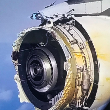
On September 30, 2017, Air France Flight 066 departed Paris Charles de Gaulle Airport bound for Los Angeles with 497 passengers and 24 crew aboard. The fan rotor on engine No. 4 — the outboard engine on the right wing — separated during climb from Flight Level 370.
Roughly five hours into the flight, while cruising at 37,000 feet, the No. 4 engine stalled, ejecting its front fan and cowling midair. The titanium fan hub fractured into at least three pieces due to a previously undetected cold dwell fatigue crack, ejecting massive fragments from the engine. Two major parts were launched violently — one upward, one downward — destroying the forward cowling and separating the entire air inlet, which fell onto Greenland’s ice sheet. Remarkably, no passengers or crew were injured.
The fracture surface exhibited a matte, granular texture consistent with cold dwell fatigue — a rare type of failure initiated by slow crack growth under low stress at high altitude. The crew diverted to Goose Bay airport in Canada after an uncontained engine failure. The aircraft landed safely.
Recovery of evidence was extraordinarily difficult. The BEA investigation involved a technically challenging search for fan-hub components from the Engine Alliance GP7200 powerplant, buried in deep snow in remote Greenland — parts which were only recovered 21 months after the accident.
The final BEA report, published in September 2020, delivered a sobering conclusion. The GP7200 engine was built by Engine Alliance, a consortium of General Electric and Pratt & Whitney, using titanium alloy Ti-6-4. The analysis clearly emphasized that the incident was no fault of the engine manufacturer or Airbus. At the time, the scientific community was not aware of Ti-6-4’s susceptibility to cold dwell fatigue.
The failure timeline was equally alarming. The crack formed 1,850 cycles into the part’s 15,000-cycle design life and expanded over the next 1,650 cycles due to dwell fatigue until the part failed. In other words, a crack that was invisible for hundreds of cycles ultimately caused an uncontained failure at less than one-quarter of the component’s certified life.
The factors likely to have contributed to the accident include: the engine designer’s and manufacturer’s lack of knowledge of the cold dwell fatigue phenomenon in the titanium alloy Ti-6-4; absence of instructions from the certification bodies about taking into account macro-zones — colonies of similarly oriented alpha grains — and the cold dwell fatigue phenomenon in the critical parts of an engine when demonstrating conformity; and absence of non-destructive means to detect the presence of unusual macro-zones in titanium alloy parts.
The Microstructural Foundation: Macro-Zones and Micro-Textured Regions
To understand dwell fatigue, one must first understand how titanium alloys are processed — and what can go wrong during forging.
Ti-6Al-4V has a hexagonal close-packed (HCP) alpha phase and a body-centered cubic beta phase. During thermomechanical processing such as forging, grains in the alpha phase can align their crystallographic c-axes in preferred directions, forming colonies of grains with similar orientations. These clusters, ranging from a fraction of a millimeter to centimeters in extent, are called macro-zones or micro-textured regions (MTRs).
Metallurgy aims at producing isotropic materials that have the same properties in every direction. Sometimes, however, anisotropic zones develop, creating local fragility. In HCP titanium, plastic slip is not equally easy in all crystallographic directions. Grains whose c-axis is aligned perpendicular to the applied load are “soft” — they have favorable Schmid factors for prism slip. Grains whose c-axis is aligned parallel to the loading direction are “hard” — they are poorly oriented for easy slip. When macro-zones place soft and hard grains in close proximity, the stage is set for the dwell fatigue mechanism.
Dwell fatigue initiating facets form at the interface between hard grains that are poorly oriented for slip and soft grains that are well oriented for slip. Regions of common orientation, termed macrozones, arising from the prior beta grains, promote such nearest-neighbor pairs and therefore promote dwell fatigue cracking.
An increase in the risk of having large macro-zones with increased intensity in large Ti-6-4 forgings is associated with bigger engines and, in particular, bigger fans. The very trend toward higher-thrust turbofans — with larger, heavier discs — inadvertently increased the risk of encountering the critical microstructural condition.
The Load-Shedding Mechanism
The dwell fatigue damage process operates at the grain scale and involves a sequence of interconnected events: time-dependent plasticity in a soft grain, stress redistribution to an adjacent hard grain, dislocation pile-up, and ultimately facet crack nucleation.
For dwell fatigue, it has been well accepted that load shedding between neighboring soft and hard grains is the dominant mechanism driving crack nucleation. The strain incompatibility between the soft-hard grain pair arises from significant creep in the soft grain during the dwell period, which is fundamentally related to the load shedding.
The sequence unfolds as follows. During the dwell period — the hold time at peak load — the soft grain, well oriented for prism slip, deforms plastically and relaxes its stress. The local stress in the hard grain increases with increasing dwell time and strain rate sensitivity. The load that the soft grain can no longer carry is transferred — shed — into the neighboring hard grain, which, poorly oriented for slip, must carry the additional stress elastically. With each load cycle and dwell, the peak stress in the hard grain ratchets upward.
Severe plastic deformation can be accumulated during the dwell period in the soft unit, which causes the stress to be redistributed to the neighboring hard unit — a phenomenon referred to as load shedding.
The Stroh Pile-Up Model and Facet Nucleation
The theoretical framework for understanding dwell fatigue crack initiation is grounded in the Stroh dislocation pile-up model, first proposed by A. N. Stroh in 1954. In classical Stroh theory, dislocations gliding on a slip plane in one grain pile up at a grain boundary, and the stress concentration at the head of the pile-up can nucleate a crack in the adjacent grain.
The Stroh pile-up model provides support for the dominant hypothesis for the rationalization of dwell fatigue crack nucleation in Ti alloys, and elaborates the underlying dislocation phenomena that result from load shedding and lead to basal faceting.
In the dwell fatigue context, dislocations accumulate in the soft grain on prism slip planes. A high density of prism pile-ups is observed by dual slip, together with the nucleation of edge dislocations in the soft grain of a highly misoriented grain pair, increasing the possibility of cracking. The stress concentration developed by such pile-ups is found to be higher in dwell fatigue — where pile-ups are single-ended — than in conventional low-cycle fatigue, where they are double-ended.
The result is a concentrated stress acting on the basal plane of the neighboring hard grain. Analytical modeling shows that the maximum normal stress produced on the hard grain in dwell fatigue by this pile-up is near-basal, approximately 2.5 degrees to the (0002) plane. When this normal stress exceeds a critical threshold, a quasi-cleavage facet crack nucleates on the basal plane of the hard grain — a characteristic signature that metallurgists look for on dwell fatigue fracture surfaces.
Restriction of rigid body rotation from neighboring grains can further enhance load shedding. Load shedding is stronger when the soft-hard grain pair is embedded inside the material rather than at the free surface — which helps explain the mechanism by which dwell fatigue cracks tend to nucleate from the sample’s interior rather than the free surface.
Creep at Room Temperature: The Counterintuitive Driver
Engineers are well acquainted with creep at elevated temperatures — the slow, time-dependent plastic deformation that limits the life of turbine blades and discs in the hot section. It is far less intuitive that creep operates meaningfully at room temperature in titanium, yet this is precisely what drives cold dwell fatigue.
Titanium alloys generate creep deformation at room temperature, where T/Tm is approximately 0.15 — a very low homologous temperature. This creep is considered to affect the reduction in fatigue life in cold dwell fatigue tests. Rupture cycle count decreases with increasing dwell time.
Room temperature creep is thought to be responsible for load shedding. Crystal plasticity modeling predicts a large strain accumulation in the hard grain due to load shedding from the soft grain. This is a kind of transient creep process in which the creep rate decreases continually with time. This creep is not expected to be associated with diffusion-mediated mechanisms such as dislocation climb, as the deformation occurs in the vicinity of room temperature. Transmission electron microscopy studies show that dislocation glide in the form of planar slip is responsible.
The key distinction from high-temperature creep is the mechanism. At elevated temperatures, creep is driven by vacancy diffusion and dislocation climb. At room temperature in titanium, the operative mechanism is thermally-assisted dislocation glide — the escape of dislocations from obstacles, controlled by applied stress and the thermal activation energy of slip. Fatigue loading above a threshold stress produces slip in soft grains, leading to strong dislocation pile-ups at boundaries with hard grains.
This transient, plasticity-driven creep response is what makes the dwell period so damaging. Without a hold, the soft grain does not have sufficient time to relax and shed its load. With a hold of even 60 to 120 seconds — representative of an aircraft cruising at altitude — significant load redistribution occurs.
Temperature Effects on Dwell Fatigue Life
The relationship between temperature and dwell fatigue life in titanium is nonmonotonic and somewhat paradoxical: modest temperature increases from room temperature can actually worsen dwell sensitivity before eventually alleviating it at higher temperatures.
Metal alloys used for aircraft engines are often expected to operate at over 300°C (572°F). However, if the motor performs at a lower temperature than that, it becomes susceptible to cold dwell fatigue, significantly reducing the expected engine cycles to failure.
Temperature significantly affects load shedding through its influence on the strain rate sensitivity of titanium alloys, and hence their dwell sensitivity. For example, the number of cycles to failure for alloy Ti-6246 under dwell fatigue loading was approximately 10,000 at 20°C, approximately 7,300 at 80°C, and approximately 13,000 at 150°C. The minimum life near 80°C reflects a zone where thermal activation enhances creep in the soft grain without yet providing sufficient cross-slip mobility to dissipate dislocation pile-ups — maximizing the load-shedding driving force.
At higher temperatures, generally above 150–200°C, the creep rate of titanium alloys increases enough that stress relaxation becomes more distributed across multiple grains and slip systems. Pile-up stresses do not concentrate as sharply. Micromechanical evidence supports cold creep at room temperature and creep saturation of titanium alloys toward around 200°C. Above this regime, conventional high-temperature creep-fatigue interaction takes over, governed by different mechanisms.
For the cold section of a turbofan engine, the fan disc operates near ambient temperatures during climb and cruise, placing it squarely in the cold dwell danger zone. The cyclic profile — high stress at takeoff, sustained cruise at altitude, followed by unloading on descent — maps almost perfectly onto the laboratory dwell test waveform.
Microstructure and the Role of Macro-Zone Scale
Not all titanium microstructures are equally susceptible. Processing history profoundly influences the scale and intensity of macro-zones and therefore dwell sensitivity.
Small clusters of preferred crystal orientations, known as micro-textured regions (MTRs), can have a significant effect on the dwell sensitivities in Ti-6Al-4V even without severe overall texture in the material. A reduction in specimen lifetimes by approximately a factor of three was observed under dwell conditions for Ti-6Al-4V, which was less than for the highly susceptible near-alpha titanium alloys such as Ti-6Al-2Sn-4Zr-2Mo, where the dwell debit is often in excess of a factor of ten.
Stronger textures enhance load shedding and thus deteriorate service lifetime. Conversely, basketweave microstructures with multiple alpha variants are more resistant: basketweave structures with multiple alpha variants have been shown to give the lowest load shedding, with the mechanistic explanation being that the beta lath structures provide multiple, small-scale alpha variants which inhibit creep and hence stress relaxation, producing more uniform, diffuse stress distributions across the microstructure.
The forging history of a disc — temperatures, reductions, cooling rates, and subsequent heat treatment — ultimately determines whether dangerous macro-zones are present and at what scale. Larger forgings for larger fans introduce a risk of more extensive macro-zones, as was seen in the A380 accident. Electron backscatter diffraction (EBSD) can be applied to metallographic polished sections or directly from the fracture surface of failed fatigue specimens to identify MTRs. Unfortunately, no volumetric non-destructive technique existed prior to the accident that could reliably detect large subsurface macro-zones in finished forgings.
The Failure of Rainflow Counting: Why Standard Fatigue Methods Miss Dwell Damage
This is the point at which the dwell fatigue problem becomes a direct challenge to standard engineering practice.
The rainflow cycle counting algorithm, originally developed by Matsuishi and Endo in 1968, is the near-universal method for reducing a complex stress-time history to a set of counted cycles for fatigue damage summation via Miner’s rule. Rainflow counting is powerful precisely because it is agnostic to the order in which cycles occur — it extracts closed hysteresis loops from the load history and tabulates their ranges and means, regardless of sequence. This is appropriate for most structural materials, where damage per cycle depends on stress amplitude and mean stress but not on how quickly the cycle is completed.
Dwell fatigue in titanium breaks this assumption fundamentally. The damage caused by a given stress cycle is not fixed — it depends critically on how long the peak stress is held. Two load histories can produce identical rainflow matrices yet cause dramatically different fatigue lives if one involves rapid cycling and the other involves sustained holds at peak stress. The rainflow algorithm, by design, captures neither the dwell time at peak load nor the rate at which that peak is approached and departed. It is blind to exactly the information that controls dwell fatigue damage.
Stated differently: rainflow counting treats time as irrelevant once cycles are counted. Dwell fatigue is an inherently time-dependent process. The two methodologies inhabit different physical worlds.
This has direct practical consequences for the loading frequency content of a stress history. A fan disc stress spectrum that cycles slowly — as occurs at the flight-by-flight timescale of climb, cruise, and descent — dwells at high stress for minutes during each cruise segment. A bench test that applies the same stress range at 20 Hz to accumulate cycles quickly does not reproduce this dwell, and will produce a non-conservative life estimate for a dwell-sensitive material. The same rainflow matrix, applied at different frequencies, represents fundamentally different physical damage in titanium. Rupture cycle count decreases with increasing dwell time — meaning the slower the effective cycling rate, the shorter the life, all else being equal. This is the inverse of what most engineers intuitively expect, and the opposite of what a frequency-independent rainflow damage model predicts.
The implication for test and analysis practice is significant. Accelerated fatigue testing — running at elevated frequency to compress test duration — will underpredict dwell damage and produce unconservative results for susceptible titanium alloys. Any life prediction methodology based purely on a stress range versus cycles (S-N) curve and a rainflow-counted spectrum, without a dwell correction factor or a separate dwell damage term, is structurally incapable of capturing this failure mode. The A380 fan hub carried a certification analysis of exactly this type, applied to a material that turned out to be dwell-sensitive in a way the community had not anticipated. The hub passed on paper; it failed in service.
Addressing this requires either replacing rainflow-based methods with mission-profile-aware cycle definitions that explicitly track hold time at peak stress, or supplementing rainflow damage with a parallel dwell damage integral — analogous in spirit to the creep damage terms used in high-temperature life assessment (such as in ASME Boiler and Pressure Vessel Code time-fraction creep-fatigue interaction rules), but calibrated for the room-temperature grain-scale creep mechanism specific to titanium.
Implications for Design, Certification, and Inspection
The AF066 accident led to fundamental reassessments by both EASA and the FAA. Both the European Union Aviation Safety Authority and the Federal Aviation Administration have been directed to ensure that the design, sizing, and manufacturing criteria for alloy engine parts are updated, and to adopt a new in-service inspection program to detect possible indications of cold dwell fatigue in these alloys.
The BEA noted that the lack of knowledge regarding cold dwell fatigue, combined with an absence of instructions from certification agencies about taking macro-zones into account, and an absence of non-destructive means to detect the presence of unusual macro-zones in titanium alloys, contributed to the accident. Certification bodies and engine manufacturers are currently considering how to better understand the cold dwell fatigue phenomenon and take it into account in the design of future engines.
Active research continues on ultrasonic and X-ray diffraction-based methods to map crystallographic texture volumetrically in finished forgings, as well as computational methods — crystal plasticity finite element (CPFE) modeling and discrete dislocation plasticity (DDP) — to predict life from measured microstructural inputs.
Summary
Cold dwell fatigue in titanium is a phenomenon that operates through a cascade of mechanisms spanning multiple length scales:
- Macro-zones (micro-textured regions) arise from forging and create neighborhoods of similarly oriented grains — the prerequisite for dangerous soft-hard grain pair arrangements.
- Soft-hard grain pairs develop mismatched slip resistance. Under a sustained load hold, the soft grain undergoes room-temperature creep via thermally-assisted dislocation glide, relaxing its own stress.
- Load shedding transfers this stress to the adjacent hard grain, which accommodates it elastically. Stress in the hard grain ratchets higher with each cycle.
- Stroh dislocation pile-ups accumulate at the soft-hard grain boundary, generating a stress concentration that acts perpendicular to the basal plane of the hard grain.
- When the concentrated normal stress exceeds a critical value, a basal facet crack nucleates in the hard grain — often subsurface — and propagates under subsequent dwell cycles far faster than conventional fatigue crack growth rates would predict.
- Temperature modulates this process non-monotonically, with a worst-case zone near 80°C and alleviation above approximately 200°C, placing cold-section turbine components in a vulnerable operating regime.
- Standard rainflow-based fatigue methods are blind to dwell damage. Rainflow counting discards time information and treats damage as cycle-amplitude-dependent only. Dwell fatigue is intrinsically time-dependent: the same stress range held for 120 seconds causes far more damage than the same range cycled at 20 Hz. Loading frequency content and hold time at peak stress are physically significant variables that conventional S-N plus rainflow methodology cannot capture — a gap that the A380 accident made impossible to ignore.
The Air France A380 incident over Greenland remains the starkest demonstration of these mechanisms at system scale. A fan hub designed for 15,000 cycles failed at 3,544 — not due to any manufacturing error or maintenance fault, but because a forging-induced macro-zone placed the right crystallographic combination of grains under the right dwell loading profile, and the science to predict or detect it simply did not exist. The lessons have reshaped how the aerospace industry certifies, processes, and inspects titanium rotating components — and underscore that even well-characterized structural alloys can harbor fatigue mechanisms that remain hidden until the conditions to activate them are finally encountered in service.
References: BEA Final Report BEA2017-0568 (2020); Matsuishi & Endo (1968); Stroh, A.N. (1954); Hasija et al. (2003); Evans & Bache (1994); Bache (2003); Joseph et al. (2020); Zheng et al. (2024); Xiong (2021, Oxford DPhil); ASME Boiler and Pressure Vessel Code, Section III, Appendix T.
© VibrationData — Tom Irvine
📌 Turbofan Engine Knowledge Hub
Explore additional articles on turbofan engine acoustics, vibration, structural dynamics, fatigue, flight incidents, and aircraft noise measurements: Turbofan Engine Sound, Vibration & Structural Dynamics .
I do believe Hydrogen is also a factor, only element that could move above 100-150°C
but difficult to prove and visualize