Introduction
A previous VibrationData post examined cold dwell fatigue in titanium — the phenomenon in which simply holding a moderate stress for one to two minutes causes far more damage per cycle than the same stress applied and immediately removed. The mechanism is driven by room-temperature grain-scale creep, load shedding between soft and hard grain pairs, and Stroh dislocation pile-ups. A central finding was that standard rainflow cycle counting is blind to this damage mode: rainflow discards time information entirely, yet dwell fatigue is an inherently time-dependent process.
A natural question follows: does the same concern apply to aluminum? The short answer is that aluminum does not exhibit cold dwell fatigue in the titanium sense — the physics are fundamentally different. But the broader issue raised by the titanium discussion, that time-dependent damage mechanisms can operate in parallel with cycle-counted fatigue and be missed by standard analysis, applies very directly to aluminum airframe structures. Pressurized fuselages provide the clearest illustration.
This post examines how the pressurization cycle in a commercial aircraft fuselage activates time-dependent damage mechanisms in aluminum — specifically stress corrosion cracking and corrosion fatigue — and why, as with titanium dwell fatigue, a pure rainflow-plus-Paris-Law analysis can be unconservative in ways that are difficult to detect until significant structural age has accumulated.
Why Aluminum Does Not Exhibit Cold Dwell Fatigue
Titanium’s susceptibility to cold dwell fatigue is rooted in its hexagonal close-packed (HCP) crystal structure, which produces strong crystallographic anisotropy: some grain orientations deform easily under a given load direction, others resist. This contrast between soft and hard grains, when combined with a sustained stress hold, drives the load-shedding and dislocation pile-up mechanism described in the previous post.
Aluminum is face-centered cubic (FCC). FCC metals have twelve equivalent {111}⟨110⟩ slip systems, far more than HCP titanium, so plastic deformation distributes much more uniformly across grains regardless of orientation. The strong soft-hard grain pair anisotropy that is central to titanium cold dwell fatigue simply does not arise. Aluminum also has a high stacking fault energy, which promotes dislocation cross-slip and prevents the planar pile-ups that concentrate stress at grain boundaries in titanium.
Additionally, room-temperature homologous temperature (T/Tm) for aluminum is considerably higher than for titanium — approximately 0.32 versus 0.15 — which means aluminum is inherently more susceptible to diffusion-assisted deformation at ambient conditions. This tends to spread rather than concentrate deformation, further suppressing a pile-up-based dwell mechanism.
The conclusion is clear: cold dwell fatigue, as a mechanism, is a titanium and HCP-alloy problem. Aluminum does not fail this way.
What Aluminum Does Suffer: The Pressurization Dwell
Every commercial flight subjects the fuselage skin to a pressurization cycle. On the ground, cabin pressure equals ambient. At cruise altitude, the fuselage is pressurized to an equivalent altitude of approximately 6,000 to 8,000 feet, producing a differential pressure across the skin of roughly 8 to 9 psi (55 to 62 kPa). This generates circumferential (hoop) tensile stress in the fuselage skin on the order of 10,000 to 15,000 psi (70 to 100 MPa) — a significant fraction of the yield strength of common fuselage alloys such as 2024-T3.
Each flight thus constitutes one pressurization cycle: ramp-up to cruise pressure, a sustained hold at peak stress during cruise, and ramp-down on descent. For a short-haul aircraft operating multiple legs per day, cycle accumulation is rapid. A high-frequency inter-island operator can accumulate 3,000 or more pressurization cycles per year. The cruise dwell at peak tensile stress can last anywhere from 30 minutes on a short hop to 14 hours on an ultra-long-haul sector.
For aluminum, the damage mechanisms activated by this profile are not grain-scale creep and load shedding, but rather three interacting phenomena: fatigue crack growth from stress concentrations, stress corrosion cracking, and corrosion fatigue. Each is time-dependent in ways that rainflow counting cannot capture.
Mechanism 1: Multi-Site Fatigue Damage at Stress Concentrations
Fuselage skin is not a smooth, uninterrupted sheet. It is assembled from panels joined by lap splices and butt joints, fastened with rivets. Every fastener hole is a stress concentration. Every lap joint edge introduces a geometric discontinuity. Under pressurization cycling, fatigue cracks initiate at these sites and grow incrementally with each cycle.
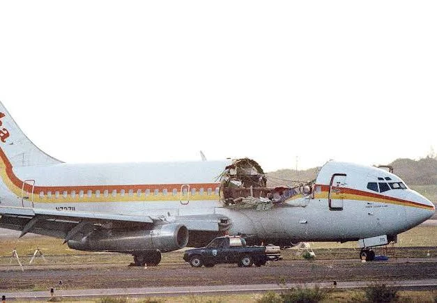
The Aloha Airlines Flight 243 accident of April 28, 1988 is the defining case study. The aircraft had accumulated 89,680 pressurization cycles by the time of the failure, far exceeding the manufacturer’s initial design expectation of 75,000 cycles for such operations. This high-cycle fatigue was particularly acute in the fuselage lap joints, where repeated pressurization and depressurization stresses initiated micro-cracks at rivet holes, allowing them to propagate undetected over years.
The failure mode was not a single dominant crack propagating to critical length — it was something more insidious. The fuselage lap splices were prone to develop Multi-Site Damage (MSD), leading to Widespread Fatigue Damage (WFD). An insidious feature of MSD is that many small, hard-to-detect cracks can link up rather suddenly to form a long, critical crack. The advanced stages of MSD can result in Widespread Fatigue Damage, a condition where the airplane structure is no longer able to sustain the required residual strength loads.
The structural design had a compounding vulnerability. Once disbonding of the lap splice occurred, the fuselage pressurization loads that were intended to be transferred through the adhesive bond were instead transferred through the rivets. Since the countersink for the rivet head went through the entire thickness of the upper skin, creating a knife edge, a higher than typical stress concentration resulted. The combination of effects from the high stress concentration, the rivet load transfer, and the far-field stress levels led to the development of fatigue cracks at many adjacent or neighboring rivet locations.
Laboratory analysis of the torn metal showed the classic signs of fatigue: striations indicating crack growth over time with each pressurization cycle, and evidence of crevice corrosion in the joint which accelerated the crack growth. The crack growth rate had been enormously amplified by the corrosive Hawaiian marine environment — which brings us to the second and more directly time-dependent mechanism.
Mechanism 2: Stress Corrosion Cracking — The Aluminum Analogue of Dwell Damage
Stress corrosion cracking (SCC) is the aluminum structural failure mode most analogous, in its time-dependence, to titanium cold dwell fatigue. It is not a cycle-counted phenomenon — it is a time-at-stress phenomenon. The longer a susceptible aluminum alloy is held under sustained tensile stress in a corrosive environment, the more crack advance occurs, independent of whether any additional load cycles are applied.
Stress corrosion cracking in 7xxx series aluminum alloys is not a single-cause failure. It requires the simultaneous presence of three conditions: sustained tensile stress, a susceptible microstructure, and a corrosive environment, particularly humid or marine atmospheres. Remove any one of these factors and SCC cannot proceed. In practice, aircraft structural components in service accumulate all three concurrently, which is why SCC remains one of the most critical failure threats to airframe integrity.
The dominant mechanism at the crack tip is hydrogen embrittlement. Moisture at the crack tip or grain boundary undergoes electrochemical reduction, generating nascent hydrogen atoms that diffuse into the alloy lattice and accumulate at grain boundaries, precipitate interfaces, and crack-tip stress fields. This causes brittle intergranular fracture at stresses far below the material’s yield strength.
The critical point for life assessment is that SCC crack advance is driven by time under load, not by load cycles. A fuselage on an overnight ground stop — unpressurized but exposed to humid salt air, with residual stresses from prior pressurization and fastener installation — can accumulate SCC damage without completing a single additional flight cycle. The rainflow matrix for that ground stop contains no cycles at all. Yet material damage has occurred.
The 7xxx alloys in peak-aged tempers, like 7075-T6 or 7050-T7451, are particularly prone to SCC in the presence of water or salt, especially if they contain coarse grain-boundary precipitates or precipitate-free zones that promote localized attack. Measures like over-aging to more ductile tempers, or using newer alloys with refined grain-boundary precipitates, can improve SCC resistance of 7xxx alloys.
This is why the heat treatment temper of high-strength aluminum airframe components is not merely a strength specification — it is a life-limiting variable. The same alloy composition in the T6 temper (peak-aged, highest strength, most SCC-susceptible) and the T73 temper (over-aged, lower strength, far more SCC-resistant) can have dramatically different service lives in the same environment under the same sustained stress. A pure S-N fatigue analysis based on tensile properties captures none of this distinction.
Mechanism 3: Corrosion Fatigue — When Environment and Cycles Interact
Corrosion fatigue is the third mechanism, and it acts as a force multiplier on the cycle-counted fatigue damage that standard analysis does predict. When fatigue crack growth occurs in the presence of a corrosive environment, crack growth rates are dramatically higher than in dry air or laboratory conditions.
Fatigue crack growth rates in aluminum alloys are lowest in vacuum, followed by those in ambient air, and are highest in salt solution. Depending on applied stress intensity, the fatigue crack growth rates in air are as much as two orders of magnitude higher than those in vacuum. The fatigue crack growth rates obtained in salt solution are up to an order of magnitude higher than those obtained in ambient air.
Two orders of magnitude in crack growth rate — for the same stress intensity range, the same cycle count — is not a second-order correction. It is the difference between a crack taking decades to reach critical length and the same crack reaching critical length in a few years. Standard damage-tolerant fatigue analysis of an aluminum fuselage uses a Paris Law crack growth rate measured under controlled laboratory conditions, typically in ambient air. If the actual operating environment involves salt-laden humid air infiltrating lap joints and fastener holes — as it does in maritime operations, coastal bases, or aircraft that regularly fly through rain and condensation — the laboratory-derived crack growth rate can be unconservative by one to two orders of magnitude.
Moisture and salt-laden air entered the lap joints and remained trapped. Over time, corrosion attacked the aluminum beneath the surface, thinning material where it could not be seen. Pressurization cycles then drove fatigue cracks from multiple rivet holes simultaneously. The cracks grew in parallel rather than as a single dominant flaw. Maintenance inspections focused on finding long, visible cracks or isolated corrosion, not widespread microscopic damage.
The time-dependence of corrosion fatigue is particularly significant for the cruise dwell. During the sustained hold at cruise altitude, crack tips that are exposed to trapped moisture or condensation undergo electrochemical attack. The stress intensity at the crack tip during the dwell is not cycling — yet the environment is still advancing the crack through anodic dissolution and hydrogen embrittlement. When the next pressurization cycle begins, the effective crack length is longer than a pure mechanical fatigue analysis would predict, and the next increment of crack growth is correspondingly larger.
The Rainflow Blind Spot Revisited: Aluminum Edition
The same methodological limitation identified in the titanium dwell fatigue discussion applies here, albeit through entirely different physical mechanisms.
Rainflow cycle counting applied to a fuselage pressurization history correctly counts the number of pressure cycles and their amplitudes. What it cannot capture is:
- The duration of the cruise dwell. A one-hour flight and a fourteen-hour flight produce the same single pressurization cycle in a rainflow matrix. They expose the structure to very different durations of sustained tensile stress, during which SCC crack advance and corrosion fatigue crack tip attack accumulate in proportion to time, not cycle count.
- The environment during the dwell. Rainflow counting records stress magnitude, not the chemical environment at the crack tip. Two aircraft flying the same routes with the same cycle counts may have dramatically different corrosion fatigue crack growth rates depending on whether lap joints are sealed, whether drain holes are functional, and whether the aircraft regularly sits in humid coastal environments between flights.
- Ground dwell damage. An aircraft sitting unpressurized at a coastal airport overnight, with residual stresses present and humid salt air infiltrating structural cavities, accumulates SCC damage that appears nowhere in the pressurization cycle count. The rainflow matrix for a ground stop is empty. The material damage is not.
- The interaction between corrosion damage and subsequent fatigue cycling. Corrosion thinning at rivet holes and in lap joint bondlines reduces the net section carrying the pressurization load, increasing the local stress intensity for all subsequent fatigue cycles. A rainflow-based analysis that was calibrated on pristine material properties progressively underestimates damage as the structure ages and corrodes.
Aloha Airlines’ maintenance program did not account for the severe operating environment of the aircraft, which was prone to corrosion. The airline’s technicians often overlooked corrosion as a normal operating condition, failing to recognize the long-term risks. The maintenance check strategy relied on flight hours rather than flight cycles, a crucial factor in fatigue crack initiation. This is a direct institutional expression of the same blind spot: a time-and-environment-dependent damage process being assessed by a cycle-and-hours-based methodology.
The Hoop Stress Geometry and Why It Matters
A fuselage under pressurization loads behaves as a thin-walled pressure vessel. The circumferential hoop stress in the skin is given by the familiar thin-wall formula:
σhoop = ΔP · R / t
where ΔP is the cabin differential pressure, R is the fuselage radius, and t is the skin thickness. For a typical narrow-body fuselage with a 74-inch (1.88 m) radius, 0.036-inch (0.91 mm) skin, and 8.6 psi (59 kPa) differential, hoop stress is approximately 13,500 psi (93 MPa). This stress is applied uniformly around the circumference — meaning every lap joint, every rivet row, and every fastener hole on the fuselage barrel is simultaneously loaded to this level for the duration of each cruise segment.
The axial (longitudinal) stress from pressurization is half the hoop stress — approximately 46 MPa for the same geometry. The fuselage skin is therefore in biaxial tension throughout cruise, with the hoop direction being the primary fatigue and SCC loading axis. Lap splices, which run longitudinally, are oriented to transfer hoop load across the joint — making them the most critically loaded structural detail in the fuselage and the primary site for both MSD fatigue cracking and SCC initiation.
Lessons from Aloha 243 and the Aging Aircraft Program
The Aloha Airlines accident prompted fundamental changes to how the aviation industry treats aging aluminum airframes. In the immediate aftermath, the U.S. Congress passed the Aviation Safety Research Act of 1988, which strengthened the FAA’s oversight of aging aircraft and mandated research into better inspection techniques. The FAA launched the National Aging Aircraft Program, and both Boeing and the FAA issued new directives to inspect and modify aircraft with high usage.
Boeing redesigned the fuselage lap joints in the 737 Next Generation series, incorporating thicker skin gauges, widened tear straps for better load distribution, reduced joint eccentricity to minimize bending stresses, and precision machine-countersunk rivets for improved hole fill and fatigue resistance. These changes were validated through full-scale fatigue testing to 225,000 cycles — three times the design service objective — and demonstrated significantly lower crack initiation rates compared to earlier models.
The regulatory response also addressed the environment-dependence of the damage process more explicitly than previous frameworks had. Mandatory corrosion prevention and control programs (CPCPs) were introduced, requiring operators to apply corrosion inhibitors, clean aircraft surfaces regularly, and pay specific attention to areas susceptible to moisture ingress. The implicit acknowledgment was that cycle counting alone was insufficient — the time-dependent corrosion damage component had to be managed as a parallel, independent degradation process.
Connecting the Two Posts: A Unified View of Time-Dependent Structural Damage
Placing the titanium cold dwell fatigue discussion alongside the aluminum fuselage discussion reveals a common structural insight, even though the physical mechanisms are entirely different.
In both cases, a time-dependent damage process operates in parallel with — and is not captured by — conventional cycle-counted fatigue analysis:
- In titanium cold sections, room-temperature grain-scale creep during the load hold drives load shedding and Stroh pile-up stress concentration, initiating basal facet cracks at lives far below the S-N prediction. The damage rate depends on hold duration, temperature, and microstructure — none of which appear in a rainflow matrix.
- In aluminum fuselages, sustained tensile stress during the cruise dwell drives SCC crack advance through hydrogen embrittlement at grain boundaries, while the corrosive environment simultaneously accelerates fatigue crack growth rates by one to two orders of magnitude relative to laboratory air conditions. The damage rate depends on time at load, environmental chemistry, and temperature — again, none of which appear in a rainflow matrix.
In both cases, accelerated fatigue testing conducted at elevated frequency to compress test duration is unconservative: it eliminates the very dwell that drives the dominant damage mechanism. In both cases, a component can pass conventional fatigue certification analysis and still fail prematurely in service once the time-dependent mechanism has accumulated sufficient damage.
The engineering lesson is not that rainflow counting is wrong — it remains the appropriate tool for cycle-dependent fatigue damage in materials and conditions where time-dependent mechanisms are inactive or negligible. The lesson is that engineers must first establish whether time-dependent damage mechanisms are potentially active for the material, environment, and loading profile under consideration, before defaulting to a pure cycle-counting framework. When they are active, supplementary analysis methods are required: dwell correction factors, time-fraction creep-fatigue interaction rules, corrosion-adjusted crack growth rates, or mission-profile-aware life models that explicitly track hold time and environmental exposure.
Summary
Pressurized aluminum fuselages do not experience cold dwell fatigue in the titanium sense — the FCC crystal structure and slip system isotropy of aluminum prevent the grain-scale load shedding mechanism that drives that failure mode. However, the pressurization cycle subjects aluminum fuselage structure to a sustained tensile dwell at cruise that activates two time-dependent damage mechanisms — stress corrosion cracking and corrosion fatigue — that are not captured by standard rainflow cycle counting:
- Multi-site fatigue damage at rivet holes and lap joints grows with each pressurization cycle, but at rates that depend strongly on the corrosive environment — not the laboratory air conditions used to calibrate Paris Law crack growth models.
- Stress corrosion cracking in high-strength aluminum alloys (particularly 7xxx series in peak-aged tempers) advances under sustained tensile stress in the presence of moisture and salt, independent of additional load cycling. Ground dwell in humid environments is damaging even when the aircraft is not flying.
- Corrosion fatigue multiplies fatigue crack growth rates by one to two orders of magnitude relative to dry conditions, making environment a first-order life variable that pure cycle counting ignores entirely.
The Aloha Airlines Flight 243 accident of 1988 — an 18-foot section of fuselage separating from a Boeing 737 at 24,000 feet after 89,680 pressurization cycles — is the canonical demonstration of what happens when these time-dependent mechanisms accumulate beyond what a cycle-based maintenance and inspection framework can detect. The same fundamental insight that the A380 titanium dwell fatigue accident revealed three decades later applies here: when time-dependent damage is active, any methodology that discards time information will eventually be surprised by the structure.
This post is a companion to: Titanium Dwell Fatigue: A Hidden Threat in the Cold Section.
References: NTSB Aircraft Accident Report AAR-89/03, Aloha Airlines Flight 243 (1989); FAA Lessons Learned, N73711; Holroyd & Scamans, Metall. Mater. Trans. A (2011); DTIC ADA613246, Corrosion-Fatigue Cracking in Al 7075 Alloys; FAA Aging Aircraft Program (1988); Boeing 737 NG Structural Design Reports; Matsuishi & Endo (1968); Paris & Erdogan (1963).
© VibrationData — Tom Irvine