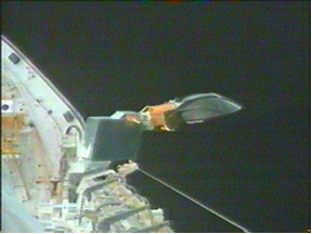
Figure 1. Space Shuttle Orbiter Ku-band Antenna
Introduction
Mechanical vibration is usually undesirable in a structure because it can lead to fatigue and other types of failures. Vibration does have its beneficial uses, however. For example, dither vibration was used to ensure that the Space Shuttle’s Ku-band antenna operated properly. This vibration was a concern for microgravity experiments, on the other hand.
Dither is a British colloquialism for “undecidedness.” It comes from the Middle English verb didderen meaning “to tremble.”
The term dither in engineering has several meanings, which are somewhat related. Here are four examples;
- Dither is a low level random noise added to a signal before it is quantized, so that the quantization error becomes uncorrelated with the signal itself.
- Dither is a vibration employed in some mechanical systems to avoid stiction and to ensure smooth motion. Stiction is short for static friction.
- Dither is a small vibration of a solenoid current superimposed over the average value. It has the purpose of reducing the hysteresis or sticking of a valve by keeping its moving parts vibrating.
- Dither is a forced oscillation applied to a ring laser gyro so that its sensed rotation rate seldom passes through the region where the two counter-propagating laser beams lock together.
All four share a common purpose. Each adds a known, benign disturbance in order to keep the system away from a nonlinearity that would otherwise dominate its behavior.
Historical Background
The following account is based on an article by Nika Aldrich.
The British naval air fleet had problems with their navigation systems during World War II. These systems were analog computers that used cranks, gears, and cogs, somewhat similar to the mechanisms in an antique grandfather clock. Unfortunately, the gears and cogs would operate in a sluggish manner due to internal static friction. The system was thus difficult to calibrate prior to flight.
The navigation systems, however, gave better performance once the aircraft was airborne.
Engineers determined that the vibrations from the plane’s engines were in effect “lubricating” the cogs and gears, so that the system worked more properly and predictably.
This “noise” added to the system helped the accuracy of the system by removing the opportunity for the gears to stick. As a result, the British installed small motors on their navigation systems to vibrate the mechanisms on the ground during preflight calibration.
The vibration of the motors added to the navigation systems provided “dither” to help the rigid cogs and gears operate more fluidly.
This story is repeated widely in the audio and controls literature. It illustrates the principle well, although the primary documentation for it is thin. It is best treated as an instructive anecdote rather than as a citable case history.
Why Dither Reduces Error
Friction between two dry or lightly lubricated surfaces is not a smooth function of velocity. The force needed to start motion, the breakaway or static friction, is larger than the force needed to sustain it. The friction curve is therefore discontinuous at zero velocity.
A mechanism operating near zero velocity lives on that discontinuity. Small commands produce no motion at all until the accumulated force exceeds breakaway, at which point the mechanism lurches, overshoots, and sticks again. The input-output curve becomes a staircase with a deadband at the origin. The error is not random. It is a systematic bias whose sign depends on the direction of the last motion, and it does not average away with time.
Now superimpose a small oscillation. The relative velocity at the sliding interface no longer sits at zero. It sweeps back and forth through the friction curve many times per second, and the mechanism spends almost none of its time at the discontinuity. The friction force averaged over one dither cycle becomes a smooth, single-valued function of the slowly varying command.
This is the key point, and it holds in every application of dither. Dither does not reduce friction and it does not add energy to the useful signal. It moves the operating point away from a nonlinearity and lets the rest of the system see a well-behaved average instead. The performance gains follow from that:
- The deadband is removed, so small commands produce proportional motion.
- Hysteresis is reduced, so the response no longer depends on the direction of approach.
- Repeatability improves, which is why the wartime units could finally be calibrated on the ground.
- A systematic bias is converted into a small zero-mean ripple at the dither frequency, which downstream filtering can remove.
- Limit cycling and hunting in a servo loop are suppressed, since the loop no longer has to break stiction on every correction.
The dither frequency must be fast relative to the bandwidth of the useful signal, so that the control loop sees only the average. It must also be slow enough that the moving parts actually respond, since a dither the mechanism cannot follow accomplishes nothing. The dither therefore lands in a band above the control bandwidth and below the first structural resonance of the moving element.
Ring Laser Gyro Dither
The clearest modern example of dither as an error reduction technique is the ring laser gyro, or RLG.
An RLG measures angular rate using the Sagnac effect. Two laser beams circulate in opposite directions around a closed optical path, typically a triangle or square of bored glass with mirrors at the corners. When the assembly rotates about the axis normal to the path, one beam travels a slightly longer optical distance than the other. The resonant frequencies of the two beams separate, and the interference fringes are counted at a detector. The RLG has no spinning mass, and therefore no friction and none of the mass-unbalance drift terms of a conventional mechanical gyro.
The RLG has one serious defect. At very low rotation rates the two optical frequencies are close together, and backscatter from the mirrors couples them. Below a threshold rate the two beams pull into a common frequency, the fringe pattern stops moving, and the gyro reports exactly zero rate. This is called lock-in.
Lock-in is the optical equivalent of stiction. It is a deadband centered on the quantity the instrument most needs to measure, and it does the same kind of damage. A vehicle turning slowly through the deadband has its rotation reported as zero, and because an inertial navigation system integrates rate to get attitude, the missing rotation becomes a heading error that grows without bound and corrupts the position solution through the misresolved accelerometer channels. As Siuru and Shaw put it in 1985, lock-in limits the accuracy of the laser gyro at exactly the low turn rates that matter most.
The production fix is dither. The gyro block is twisted back and forth about its sensitive axis on a flexure, at the mechanical resonance of the suspension, typically a few hundred hertz. Because the dither is itself a rotation, it adds directly to the rate the gyro senses. The peak dither rate is
$$\dot\theta_{max}=2\pi f_d\,\theta_d$$
where $f_d$ is the dither frequency and $\theta_d$ is the dither amplitude. A representative amplitude of 60 arc-seconds at 400 Hz gives a peak rate of about 42 deg/sec. A navigation grade lock-in threshold on the order of 0.05 deg/sec is then some 800 times smaller than the dither, and the gyro spends less than 0.1 percent of each dither cycle inside the deadband. The dither rotation is subtracted out in software, since its amplitude and phase are known from a pickoff on the flexure.
Two refinements are worth noting.
First, a purely sinusoidal dither still passes through zero rate twice per cycle, and a small phase error accumulates at each turnaround. This residual is called dynamic lock-in. Production units therefore add a small random modulation to the dither amplitude, so that the turnaround errors accumulate as a random walk rather than as a bias. The distinction matters: a bias grows linearly with time, while a random walk grows as the square root of time.
Second, a three-axis inertial measurement unit carries three gyros on a common block. If all three were dithered at the same frequency they would couple mechanically through the block and the case, and the cross-coupling would corrupt all three channels. The dither frequencies are therefore deliberately separated, and each gyro’s frequency is stamped on its housing.
Measured Dither Tones from an Inertial Navigation System
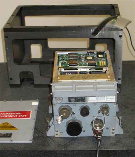
The author performed a test on an Inertial Navigation System engineering development unit in April 2007, at an aerospace company which will remain unnamed. The INS was powered so that its ring laser gyros underwent dither oscillation. The resulting sound was recorded with a microphone and a notebook PC at 44,100 samples per second, and a spectral analysis was performed.
The measured tones agreed closely with the dither frequencies stamped on the individual gyro housings, as shown in Table 1.
Table 1. INS Dither Frequency Results
| Spec (Hz) | Measured (Hz) | Comment |
| 521 | 526 | Gyro 1 |
| 574 | 573 | Gyro 2 |
| 619 | 620 | Gyro 3 |
| – | 1194 | Not an integer harmonic of any dither frequency |
| – | 1239 | 2X harmonic of the 620 Hz dither |
The three tones are close enough together that the recorded sound has a strong beat, with an envelope repeating at 47 Hz from the 620 minus 573 Hz and 573 minus 526 Hz differences, and at 94 Hz from the 620 minus 526 Hz difference. The beat is audible and it is obvious in the time history, but the narrowband spectrum contains no energy at 47 or 94 Hz. Summing sinusoids is a linear operation, so a combination of tones at 526, 573, and 620 Hz contains only those three frequencies. The beat is an amplitude modulation, which is a psychoacoustic effect rather than a mechanical excitation, and no structure will respond to it. Beat frequencies become real spectral lines only when a nonlinearity is present to mix them.
The Price of Dither
Dither improves the instrument that carries it, but the dither is a permanent, narrowband, always-on disturbance for everything else nearby.
The test described above was performed to explain a steady 40 Hz signal that a rotational sensor in the same INS reported both before and during the flight of a suborbital vehicle. The signal did not affect the mission results, but an unexplained persistent line in flight data is either a real structural response the models are missing or an artifact, and those two possibilities call for very different responses.
It proved to be an artifact. The INS sampled its isolated sensor block at 1200 samples per second, then averaged six samples at a time to get 200 samples per second, then averaged pairs to get 100 samples per second. The only anti-aliasing protection in that chain is the averaging itself, and a moving average is a poor anti-aliasing filter. Its gain returns to unity at every integer multiple of the sample rate, and 1200 Hz is precisely the frequency that folds down to DC. The three primary dither tones at 526, 573, and 620 Hz are attenuated by roughly 24 to 26 dB, but the 1194 and 1239 Hz components pass with less than 3 dB of loss and land at 6 and 39 Hz.
The 40 Hz signal was the 39 Hz alias of the 1239 Hz line, which is the second harmonic of the 620 Hz gyro dither. The frequencies the filter passed best were the frequencies that aliased worst. Note also that the fundamental was not the culprit: the harmonic, an order of magnitude smaller at the source, produced the artifact because it happened to sit in a passband lobe.
The practical lesson is that every tonal source on a vehicle, including the ones inside your own instruments, belongs in the aliasing analysis before the sample rate and the anti-aliasing filter are chosen.
Space Shuttle Orbiter Ku-band Antenna
The Orbiter Ku-band antenna system was used to transmit voice, data, and video images to the ground via the Tracking and Data Relay Satellite System (TDRSS).
The Ku-band antenna supplemented the S-band antenna system. The Ku-band antenna could transmit data at a higher rate than the S-band system, but the S-band antenna had a larger beam width.
The Ku-band antenna could also be used as a radar system for tracking objects in space.
This antenna was located in the payload bay. It was used only after the Orbiter had reached its orbit and opened its payload doors.
The deployed assembly consisted of a two-axis, gimbal-mounted, high-gain antenna; an integral gyro assembly; and a radio frequency electronics box.
The gimbal motors positioned the Ku-band antenna. The rate sensors determined how fast the antenna was moving.
The antenna was a parabolic dish, 3 feet in diameter, made from graphite epoxy.
Antenna Dither
The Ku-band antenna was dithered via a command signal at a frequency of 17 Hz to maintain its ability to smoothly search for and track the TDRSS satellites. This is the stiction problem of the preceding sections applied to a gimbal that must slew slowly and stop precisely, and the benefit is the same one the wartime navigation computers received.
The dithering was intermittent, depending on a number of factors.
The 17 Hz dither frequency is clearly seen in acceleration data collected on-orbit, when the dither is on, as shown in Figure 2.
The dither may also have integer harmonics at 34 and 51 Hz as shown in Figure 3.
Additional frequencies are given in Table 2. Each of these frequencies may affect the performance of microgravity experiments.
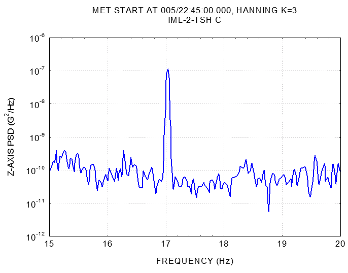
Figure 2. Power Spectral Density Plot
The overall level is 80 micro G, over the domain shown in the figure.
The data is from the STS-65 mission on the Columbia Orbiter. The Orbiter carried the International Microgravity Laboratory (IML-2).
The vibration level is a concern because it could interfere with crystal growth, dendritic solidification of molten materials, and other microgravity experiments.
Reference: NASA TM-1999-209048
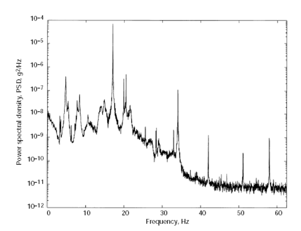
Figure 3. Power Spectral Density, STS-62 Mission
Reference: NASA TM-107032
Table 2. Vibration Frequencies Commonly Seen in Orbiter Accelerometer Data
| Freq (Hz) | Disturbance Source |
| 0.43 | Cargo bay doors |
| 3.5 | Orbiter fuselage torsion |
| 3.66 | Structural frequency of Orbiter |
| 4.64 | Structural frequency of Orbiter |
| 5.2 | Orbiter fuselage normal bending |
| 7.4 | Orbiter fuselage lateral bending |
| 17 | Ku-band antenna dither |
| 20 | Experiment air circulation fan |
| 22 | Refrigerator freezer compressor |
| 38 | Experiment air circulation fan |
| 39.8 | Experiment centrifuge rotation speed |
| 43 | Experiment air circulation fan |
| 48 | Experiment air circulation fan |
| 53 | Experiment air circulation fan |
| 60 | Refrigerator piston compressor |
| 80 | Experiment water pump |
| 166.7 | Orbiter hydraulic circulation pump |
Closing Thought
Dither is one of the few cases in which adding vibration to a system makes it work better. The gain is real and it is a gain in accuracy, not merely in smoothness: a deadband is removed, a systematic bias becomes a zero-mean ripple, and in the ring laser gyro an unbounded heading error becomes a bounded one. The cost is that the dither is then present everywhere else, in the microgravity environment of a laboratory module, in the wear rate of a valve spool, and, if the sampling scheme was not chosen with it in mind, as a persistent line in the flight data at a frequency that does not exist.
– Tom Irvine