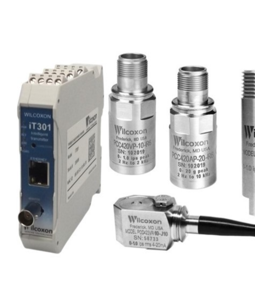
Wilcoxon Sensing Technologies 4-20 mA vibration transmitters and iT301 intelligent transmitter. Image courtesy of Wilcoxon Sensing Technologies
Machinery Vibration Monitoring: Alarm & Trip Protection
How permanently installed vibration sensors decide when to warn the operator — and when to shut the machine down.
Rotating machinery rarely fails without warning. Unbalance, misalignment, rolling-element bearing defects, looseness, and rubs all announce themselves as rising vibration long before catastrophic failure. A machinery protection system exploits this by continuously comparing measured vibration against preset thresholds. When the level crosses the first threshold, the system raises an alert so maintenance can be planned. When it crosses the second, the system initiates an automatic trip — shutting the machine down to prevent wreckage, fire, or injury.
This post covers the sensors, the metrics, the ISO severity zones used to set the thresholds, and the API 670 logic that keeps a protection system from tripping a healthy machine.
Protection vs. Condition Monitoring
The two functions are related but distinct. Machinery protection is a real-time safety function: dedicated sensors, a monitor rack, and hardwired relay outputs to the trip circuit. It must act within seconds and must be highly resistant to false trips. Condition monitoring is a diagnostic function: spectra, waveforms, and trends collected for analysts to determine why vibration is rising. A modern installation typically does both from the same sensor set, but the protection path is kept simple and deterministic.
Sensors and What They Measure
Three transducer families dominate industrial machinery monitoring:
| Sensor | Quantity | Typical Use | Typical Units |
|---|---|---|---|
| Piezoelectric accelerometer | Casing (seismic) acceleration | Rolling-element bearing machines: pumps, fans, motors, gearboxes | g or m/s²; usually integrated to velocity |
| Velocity transducer (moving-coil or internally integrated piezo) | Casing velocity | General machines, legacy installations | mm/s or in/s |
| Eddy-current proximity probe | Shaft relative displacement | Fluid-film (journal) bearing machines: turbines, compressors, large pumps | μm or mils peak-to-peak |
The choice follows the bearing type. In a fluid-film bearing machine, the shaft can vibrate severely inside the bearing while the casing barely moves, so shaft-relative displacement from a pair of orthogonal proximity probes (X-Y, typically 45° either side of vertical) is the protection parameter. Machines on rolling-element bearings transmit vibration efficiently to the casing, so a casing-mounted accelerometer or velocity sensor at each bearing housing is the standard approach. Axial (thrust) position probes protect against thrust bearing failure on large turbomachinery.
The Broadband Velocity Metric
For casing measurements, the protection parameter is almost always broadband RMS velocity over roughly 10 to 1000 Hz. Velocity is preferred because it weights machinery fault frequencies fairly evenly and correlates well with fatigue stress severity across a wide speed range. For a sinusoidal component at frequency \( f \):
$$ v_{peak} = 2 \pi f \, d_{peak} \qquad a_{peak} = 2 \pi f \, v_{peak} $$
The overall RMS level combines all spectral components:
$$ v_{RMS} = \sqrt{ \sum_{i} v_{i,RMS}^{\,2} } $$
The monitor computes this value continuously, typically over a 1-second window, and compares it against the setpoints.
ISO 20816 Severity Zones
ISO 20816-3 (successor to ISO 10816-3) defines four evaluation zones for industrial machines above 15 kW, based on broadband RMS velocity measured on non-rotating parts:
| Zone | Interpretation |
|---|---|
| A | Newly commissioned machine condition |
| B | Acceptable for unrestricted long-term operation |
| C | Unsatisfactory for continuous operation; run for a limited period until remedial action |
| D | Vibration severe enough to cause damage |
Representative zone boundary values (broadband RMS velocity, mm/s):
| Machine Group | Support | A/B | B/C | C/D |
|---|---|---|---|---|
| Group 1: Large machines, 300 kW to 50 MW | Rigid | 2.3 | 4.5 | 7.1 |
| Group 1: Large machines, 300 kW to 50 MW | Flexible | 3.5 | 7.1 | 11.0 |
| Group 2: Medium machines, 15 kW to 300 kW | Rigid | 1.4 | 2.8 | 4.5 |
| Group 2: Medium machines, 15 kW to 300 kW | Flexible | 2.3 | 4.5 | 7.1 |
Consult the current edition of the standard for the governing values for a specific machine class; special-purpose machines (turbines, reciprocating compressors, hydro units) have their own parts of ISO 20816.
Setting the Alarm and Trip Levels
ISO 20816-3 gives practical guidance. The alarm (alert) setpoint should be referenced to the machine’s own baseline, not just the generic zone table, because a well-installed machine may run far below the zone B limit:
$$ \text{ALARM} = v_{baseline} + 0.25 \, v_{B/C} $$
where \( v_{baseline} \) is the established steady-state operating level and \( v_{B/C} \) is the upper boundary of zone B. The alarm should normally not exceed 1.25 times the zone B boundary. The trip (shutdown) setpoint is tied to machine integrity rather than to the baseline — it is generally set within zone C or D, and it is recommended not to exceed:
$$ \text{TRIP} \leq 1.25 \, v_{C/D} $$
As a worked example, consider a 500 kW motor-driven pump on a rigid foundation (Group 1 rigid: B/C = 4.5 mm/s, C/D = 7.1 mm/s) with a commissioning baseline of 1.8 mm/s RMS. The alarm would be set near \( 1.8 + 0.25 \times 4.5 \approx 2.9 \) mm/s, and the trip somewhere between 7.1 and 8.9 mm/s depending on the criticality of the machine and the consequence of an unplanned shutdown.
KEY POINT: The alarm level belongs to the machine’s baseline; the trip level belongs to the machine’s integrity limit. Alarms are trending tools that buy planning time. Trips are last-resort protection, set high enough that they only fire when continued operation risks destroying the machine.
API 670: Anatomy of a Protection System
For critical turbomachinery in refineries and petrochemical plants, API Standard 670 defines the machinery protection system architecture. Several of its features address the central engineering tension — trip fast on real faults, never trip on false ones:
Two setpoints per channel. API 670 uses Alert and Danger setpoints, corresponding to the alarm and trip functions above. Alert annunciates in the control room; Danger drives the shutdown relay.
Time delays. The measured level must remain above the setpoint continuously for a short delay (commonly 1 to 3 seconds for the Danger setpoint) before the relay actuates. This rejects momentary spikes from process transients, sensor knocks, or electrical noise.
Voting logic. On the most critical machines, redundant channels are arranged in two-out-of-three (2oo3) voting: at least two of three independent measurements must exceed the Danger setpoint simultaneously to trip. A single failed or noisy sensor can then neither trip the machine nor block a legitimate trip.
Trip multiply. During startup, a machine passing through a rotor critical speed will legitimately exceed its steady-state trip level. The trip multiply function temporarily raises the setpoints (typically by a factor of 2 or 3) during the run-up so the machine can accelerate through resonance without a spurious shutdown, then restores them at operating speed.
Sensor OK checking. The monitor continuously verifies transducer bias voltage and circuit continuity. A failed sensor annunciates a “not OK” status rather than a vibration alarm, and is excluded from voting.
Practical Considerations
A few field lessons round out the picture. Establish the baseline after the machine has thermally stabilized at normal load, since alignment and clearances shift with temperature. Review setpoints after any overhaul, rebalance, or foundation repair — the new baseline may be substantially lower, and the old alarm margin correspondingly too generous. Mount accelerometers on stud or adhesive pads at the bearing housing, in the load zone where possible; magnet mounts limit usable bandwidth and are better reserved for walk-around surveys. Finally, remember that a broadband trip protects the machine but does not diagnose it: a rolling-element bearing in early-stage failure can generate defect tones that barely move the overall velocity level. Protection thresholds and spectral condition monitoring are complements, not substitutes.
References
ISO 20816-1 & 20816-3, Mechanical vibration — Measurement and evaluation of machine vibration.
API Standard 670, Machinery Protection Systems, American Petroleum Institute.
T. Irvine, Vibrationdata publications & free ebooks: https://blog.vibrationdata.com/2025/11/27/toms-ebooks/