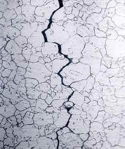

intergranular SCC of an Inconel heat exchanger tube with the crack following the grain boundaries. photo courtesy
1. Definition and Basic Mechanism
Three conditions must coexist for SCC to occur:
- A susceptible material
- Sustained tensile stress — applied, residual, or both
- A specific corrosive environment for that material-environment pair
Remove any one of the three and SCC stops. This distinguishes SCC from general corrosion (no stress required) and from classical fatigue (no corrosive environment required, cyclic rather than sustained loading).
At the microstructural level, two competing mechanisms contribute depending on the alloy and environment:
- Anodic dissolution: The corrosive environment selectively dissolves material at the crack tip, advancing the crack front along paths of high electrochemical activity — grain boundaries, precipitate interfaces, or dislocation pile-ups.
- Hydrogen embrittlement (HE): Atomic hydrogen generated by cathodic reactions diffuses into the metal ahead of the crack tip, reducing local ductility and enabling brittle fracture at stress intensities below the fracture toughness KIC.
In many high-strength alloys — particularly steels and titanium — hydrogen embrittlement dominates. In aluminum alloys, anodic dissolution at grain boundaries is the primary driver.
2. Fracture Mechanics Characterization
SCC is characterized by a threshold stress intensity factor KISCC, analogous to the fatigue crack growth threshold ΔKth. The governing condition is:
where σ is the applied net-section stress, a is crack length, and F(a/W) is the geometry correction factor. Below KISCC the crack is dormant. Above it, crack growth rate da/dt follows a sigmoidal curve with three regions:
- Region I: Steep rise in da/dt above KISCC — environmentally controlled
- Region II: Plateau — da/dt independent of KI, limited by transport of corrosive species to the crack tip
- Region III: Rapid acceleration as KI approaches KIC, transitioning to mechanical fracture
The plateau crack velocity in Region II is material and environment specific. Representative values:
| Material | Environment | Region II da/dt |
|---|---|---|
| 7075-T651 aluminum | 3.5% NaCl solution | 10−6 – 10−5 m/s |
| Ti-6Al-4V | Salt water / methanol | 10−8 – 10−6 m/s |
| 4340 steel (HRC 52) | Salt water | 10−6 – 10−4 m/s |
| 17-4 PH stainless (H900) | Chloride solution | 10−7 – 10−5 m/s |
3. Material and Environment Susceptibility
High-Strength Aluminum Alloys
The 7xxx series (7075, 7050, 7010) in the T6 temper condition is highly susceptible to SCC in humid air and salt environments. Susceptibility is primarily intergranular, driven by anodic dissolution of the zinc- and magnesium-rich grain boundary precipitates. The short-transverse (ST) grain direction — through the thickness of rolled plate — is the most vulnerable orientation.
Over-aging to T73 or T7351 temper significantly reduces SCC susceptibility by coarsening and redistributing grain boundary precipitates, at a cost of approximately 10–15% in tensile strength.
Titanium Alloys
Ti-6Al-4V is generally resistant to SCC in salt water and most service environments, but is susceptible in:
- Anhydrous methanol
- Red fuming nitric acid (RFNA) — pyrophoric risk
- Nitrogen tetroxide (N2O4) — rocket propellant oxidizer
- Certain halide solutions at elevated temperature
Hydrogen embrittlement of titanium can occur during electroplating operations (cadmium, chrome) if adequate bake-out is not performed. This is a manufacturing process control issue as much as a service environment issue.
High-Strength Steel
High-strength steels (4340, 300M, D6AC, HP-9-4-30) are susceptible to hydrogen embrittlement SCC in aqueous environments, particularly at hardness levels above HRC 40. The threshold KISCC drops sharply with increasing yield strength, such that ultra-high-strength steels (Fty > 200 ksi) may have KISCC values as low as 20–30 ksi√in compared to KIC values of 50–90 ksi√in.
Precipitation-Hardened Stainless Steels
17-4 PH and 15-5 PH in the H900 condition are susceptible to chloride-induced SCC. Over-aging to H1025 or H1150 reduces susceptibility significantly. Per NASM 1312 and aerospace contractor design standards, H900 is generally not permitted in applications involving sustained stress in chloride environments without protective coating.
4. SCC vs. Fatigue Crack Growth — Key Distinctions
| Parameter | Fatigue Crack Growth | Stress Corrosion Cracking |
|---|---|---|
| Load type | Cyclic (ΔK driven) | Sustained (KI driven) |
| Threshold | ΔKth | KISCC |
| Time dependence | Cycle-dependent | Time-dependent |
| Environment role | Accelerates growth rate | Essential — no growth without it |
| Crack path | Transgranular (typically) | Intergranular or transgranular |
| Fracture surface | Striations, beach marks | Branched, brittle appearance |
| Temperature effect | Moderate | Strong — Arrhenius relationship |
In practice, the two mechanisms interact. Corrosion fatigue — cyclic loading in a corrosive environment — produces da/dN rates significantly higher than either mechanism alone, because corrosion damage at the crack tip reduces the energy required for each fatigue cycle.
5. Interaction with Cold Dwell Fatigue in Titanium
Cold dwell fatigue (time-dependent crack advance under sustained load in Ti-6Al-4V and related alloys) and SCC share a common feature: both are driven by sustained stress rather than cyclic stress range. However, they are distinct mechanisms:
- Cold dwell fatigue operates by strain localization in favorably oriented (“soft”) grains adjacent to hard grain clusters, driven by dislocation pile-up and creep-like slip at room temperature. It does not require a corrosive environment.
- SCC in titanium requires a specific aggressive environment and typically produces a different crack path and fracture morphology.
For a titanium ejection seat fitting subject to sustained ground load in a marine environment (carrier-based aircraft), both mechanisms may operate simultaneously. A combined damage model must account for both the dwell fatigue term and an SCC term:
where DSCC is computed from the time at KI > KISCC integrated over the crack growth curve:
6. Aerospace Applications and Case Studies
F-111 Wing Pivot Fitting (1969)
The first F-111 in-service loss resulted from fracture of the D6AC steel wing pivot fitting. The failure was attributed to a pre-existing manufacturing flaw combined with hydrogen embrittlement. While primarily a fracture mechanics/quality control failure, it established the damage tolerance philosophy now codified in MIL-STD-1530 and JSSG-2006, and prompted routine inspection requirements for high-strength steel components in sustained stress applications.
7075-T6 Aluminum Structure
Numerous documented cases of SCC in 7075-T6 wing skins and fittings, particularly in short-transverse orientation, have driven the aerospace industry toward 7050-T7451 and 7075-T73 for primary structure in humid or salt environments. The transition reduced SCC failures substantially at the cost of modest strength reduction.
Landing Gear Components
High-strength steel (300M, 4340M) landing gear components operating in wheel well environments are subject to sustained tensile preload from interference-fit bushings combined with hydraulic fluid and moisture exposure. KISCC for 300M in salt water is approximately 25–35 ksi√in, well below the KIC of 60–80 ksi√in, making damage tolerance analysis essential.
7. Detection and Mitigation
Design Controls
- Select temper or heat treatment to maximize KISCC (over-age aluminum; lower hardness in steel)
- Orient grain flow so short-transverse direction is not loaded in sustained tension
- Minimize stress concentrations — generous fillet radii, smooth transitions, low Kt
- Introduce compressive residual stress via shot peening, laser peening, or low-plasticity burnishing
Environmental Controls
- Cadmium or aluminum-pigmented epoxy primer on steel and aluminum components
- Anodize plus sealant on aluminum
- Drainage provisions to prevent moisture accumulation at faying surfaces
- Avoid dissimilar metal couples that establish galvanic cells
Inspection
- Fluorescent penetrant inspection (FPI) for surface crack detection
- Eddy current inspection for near-surface cracks in aluminum and titanium
- Ultrasonic inspection (UT) for sub-surface crack detection in thick sections
- Inspection intervals derived from fracture mechanics: set so that a crack growing at the Region II da/dt rate cannot reach critical size between inspections
8. Damage Tolerance Life Assessment
The SCC life assessment parallels the fatigue damage tolerance approach of MIL-STD-1530D:
- Establish initial flaw size from inspection capability (e.g., 0.05 in. surface crack)
- Compute KI as a function of crack size for the sustained load spectrum
- Integrate da/dt from KISCC to critical crack size acr = (KIC/βσ)2/π
- Divide total time by scatter factor (typically 2–4 for SCC life assessment)
- Set inspection interval to ½ the calculated SCC life from initial flaw
The critical crack size at final fracture is:
where β is the geometry correction factor and σ is the net section stress.
9. Summary
| Attribute | Description |
|---|---|
| Required conditions | Susceptible material + sustained tensile stress + corrosive environment |
| Primary mechanisms | Anodic dissolution (aluminum); hydrogen embrittlement (steel, titanium) |
| Fracture mechanics parameter | KISCC — threshold stress intensity for SCC |
| Crack growth form | Time-dependent da/dt; three-region sigmoidal curve |
| Most susceptible aerospace alloys | 7075-T6 Al; high-strength steel > HRC 40; 17-4 PH H900 |
| Primary mitigation | Temper selection; compressive residual stress; protective coatings; drainage design |
| Life assessment method | Fracture mechanics integration of da/dt from initial to critical crack size |
| Governing standards | MIL-STD-1530D; JSSG-2006; ASTM G47 (Al SCC test); ASTM G49 |
References
Speidel, M.O., “Stress Corrosion Cracking of Aluminum Alloys,” Metallurgical Transactions A, Vol. 6A, 1975.
Gangloff, R.P., “Hydrogen Assisted Cracking of High Strength Alloys,” Comprehensive Structural Integrity, Vol. 6, Elsevier, 2003.
MIL-STD-1530D, Aircraft Structural Integrity Program (ASIP), 2016.
JSSG-2006, Aircraft Structures, Joint Service Specification Guide, 1998.
ASTM G47, Standard Test Method for Determining Susceptibility to Stress-Corrosion Cracking of 2xxx and 7xxx Aluminum Alloy Products.
Irvine, T., Fatigue Loads on Fighter Jet Ejection Seat Metal Components, VibrationData Blog, 2026.
See also: Five Notable Stress Corrosion Cracking Case Histories
Looking for a deep dive on this topic? Explore our comprehensive guide and resource collection on the Residual Stress & Structural Integrity Hub.
2 thoughts on “Stress Corrosion Cracking”