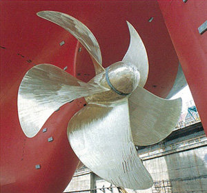
Image credit: Merchant Navy Decoded — Propeller of Ship
Walk along any harbor dry dock and you will notice that ship propellers almost always have between three and six blades, with four and five being the most common for merchant vessels. The blade count is not arbitrary. It is a deliberate compromise among three competing demands: hydrodynamic efficiency, cavitation avoidance, and structural vibration. The third item is the focus of this post, because the propeller is the dominant source of hull vibration on most ships, and blade count is one of the naval architect’s primary levers for controlling it.
The Efficiency Case for Fewer Blades
On pure open-water efficiency, fewer blades win. Each blade operates partly in the induced flow field of its neighbors, so fewer, larger blades experience less blade-to-blade interference. Fewer blades also mean less total blade surface area for a given thrust, which reduces frictional drag losses. In the idealized limit, a single-bladed propeller would be the most efficient, and two-blade propellers do appear where efficiency dominates and thrust loads are light, such as sailing yacht auxiliaries, where the stopped blades can also be aligned behind the keel to minimize drag under sail.
Thrust Loading and Cavitation Push the Other Way
A large containership may deliver more than 60 MW through a single shaft. The propeller must generate that thrust without the suction-side pressure falling below the vapor pressure of seawater, which would cause cavitation, with its attendant erosion, thrust breakdown, broadband noise, and impulsive pressure loading on the hull plating above the propeller.
The local cavitation margin is characterized by the cavitation number
$$ \sigma = \frac{p_0 – p_v}{\tfrac{1}{2}\rho V^2} $$
where $p_0$ is the ambient static pressure at the blade, $p_v$ is the vapor pressure, $\rho$ is the water density, and $V$ is the local inflow velocity. Keeping the blade loading low enough to avoid cavitation requires sufficient total blade area. When the propeller diameter is capped by the ship’s draft and by hull clearance requirements, the practical way to add blade area and reduce the load per blade is to add blades. Heavily loaded ships therefore trend toward five or six blades.
Blade-Pass Frequency and Hull Vibration
The propeller operates in the hull’s non-uniform wake. As each blade sweeps past the velocity deficit at the top of the propeller aperture, its angle of attack and loading change abruptly. The result is a set of unsteady thrust, torque, and hull pressure pulses at the blade-pass frequency and its integer harmonics.
Blade-Pass Frequency
$$ f_{bp} = \frac{N \, \Omega}{60} \;\; \text{Hz} $$
where $N$ is the number of blades and $\Omega$ is the shaft speed in RPM. A six-blade propeller turning at 84 RPM excites the hull at $f_{bp} = 8.4$ Hz, with harmonics at 16.8 Hz, 25.2 Hz, and so on. Shaft-rate excitation at $\Omega / 60$ Hz is also present due to blade-to-blade manufacturing differences and shaft eccentricity.
Adding blades helps the vibration problem in two ways. First, each blade carries less mean load, so the fluctuating load per wake encounter is smaller and the excitation amplitude at each harmonic drops. Second, the blade-pass frequency rises, moving the excitation away from the low-frequency hull girder bending modes and deckhouse fore-aft modes, and up into a range where the structural response is generally lower.
The naval architect also works this problem from the resonance side. Blade counts are selected so that the blade-pass frequency and its first few harmonics avoid known hull girder, deckhouse, and shafting natural frequencies over the service RPM range. Changing from four blades to five shifts every excitation line by 25 percent, which is often enough to detune a troublesome coincidence without touching the structure.
Why Odd Blade Counts Are Often Preferred
The hull wake behind a single-screw ship is roughly symmetric about the vertical centerplane, with the strongest velocity deficit at the top of the aperture near the stern frame. With an even number of blades, two diametrically opposed blades pass through the wake peak and the bottom clearance region simultaneously, so their unsteady loads reinforce. With an odd count, the encounters stagger in time and the net excitation is reduced. This is one reason three and five blade propellers are so common, and why five is a frequent choice for ships where passenger comfort matters.
Typical Blade Counts
| Vessel Type | Typical Blade Count | Driving Consideration |
|---|---|---|
| Sailing yacht auxiliary | 2 | Minimum drag under sail |
| Workboats, tugs, small craft | 3 – 4 | Efficiency, simplicity, cost |
| Merchant ships (tankers, bulkers, containerships) | 4 – 6 | Cavitation margin at high thrust loading |
| Cruise ships, naval combatants | 5 – 6, with skew | Vibration comfort, acoustics |
| Submarines | 7+, highly skewed, or pump-jet | Minimum tonal signature, cavitation inception depth |
Fixed and Controllable Pitch Propellers
Blade count interacts with another fundamental design choice: whether the propeller is a fixed pitch propeller (FPP) or a controllable pitch propeller (CPP).
A fixed pitch propeller is a monoblock casting, typically nickel-aluminum bronze, with the blade pitch set permanently at manufacture. It is simple, robust, and hydrodynamically clean, with a small hub, a hub-to-diameter ratio of roughly 0.18, that leaves the maximum annulus available for the blades. Thrust is varied by changing shaft speed, and reversing requires stopping and reversing the engine or a reversing gearbox. Most large merchant ships with direct-drive, low-speed diesels use fixed pitch propellers.
A controllable pitch propeller mounts each blade on a rotatable spindle in an oversized hub containing a hydraulic pitch-change mechanism, actuated through the hollow shaft line. Pitch can be varied underway, from full ahead through zero thrust to full astern, at constant shaft speed. This suits ferries, tugs, offshore vessels, and any ship that maneuvers frequently, and it allows a shaft generator to run at the constant RPM needed for fixed-frequency electrical power. The prices paid are mechanical complexity, a hub-to-diameter ratio of roughly 0.24 to 0.32 that steals blade area, and root chord lengths limited by the requirement that adjacent blades clear one another as they rotate through the pitch range. Both constraints push against high blade counts, and four blades is the most common CPP configuration, with five used where vibration requirements demand it.
From a vibration standpoint the two types differ in an interesting way. An FPP ship sweeps its blade-pass frequency across a band as shaft speed changes, so the designer must clear resonances over the entire operating RPM range, but any coincidence is transient. A CPP ship running at constant RPM has a blade-pass frequency that is fixed, which makes resonance avoidance a matter of clearing a single line rather than a band. The hazard is off-design operation: at strongly reduced pitch and full RPM, the blade sections run at poor angles of attack, and cavitation and hull pressure pulses can increase markedly even though the ship is moving slowly. Combinator control, which schedules pitch and RPM together, exists largely to keep the blades near their design inflow angles and manage exactly this problem.
Propeller Materials
The dominant propeller material for large ships is nickel-aluminum bronze (NAB), typically to the composition of a Cu-9Al-4Ni-4Fe alloy such as UNS C95800. NAB offers an unusual combination of properties matched to the propeller’s load environment: good seawater corrosion resistance from its adherent alumina-rich oxide film, high resistance to cavitation erosion, good corrosion fatigue strength, excellent castability in the very large sections required, and enough ductility to allow blades bent by debris strikes or groundings to be cold or hot straightened rather than scrapped. A single casting for a large containership propeller can exceed 100 metric tons.
Manganese bronze (actually a high-tensile brass) preceded NAB and is still used for smaller and lower-cost propellers, but it is markedly inferior in cavitation erosion resistance and is susceptible to dezincification and stress corrosion cracking in polluted harbor water, which is why NAB displaced it for major vessels.
Stainless steels, including 13Cr-4Ni martensitic grades and duplex grades, are used where higher strength or better repairability by welding is desired, and for ice-class propellers where blades must survive repeated ice milling loads. Their drawbacks are susceptibility to crevice and pitting corrosion under stagnant, low-oxygen conditions, and inferior cavitation erosion behavior compared with NAB unless carefully specified.
The fatigue design problem deserves emphasis. Every wake encounter described earlier is a fatigue cycle at blade-pass frequency per blade, so a propeller blade root accumulates on the order of $10^8$ to $10^9$ cycles over a 25-year service life. This is firmly in the gigacycle regime, and the design stress must sit below the corrosion fatigue strength of the alloy in seawater, which is substantially lower than the in-air fatigue strength and does not exhibit a true endurance limit. Classification society rules for blade root thickness are, at their core, corrosion fatigue rules. Blade failures that do occur typically initiate at the root fillet on the pressure side, at casting defects, or at repair welds, and propagate by high cycle fatigue until final fracture releases the blade, an event immediately obvious from the resulting once-per-revolution unbalance vibration.
Composite propellers, typically carbon fiber reinforced polymer blades on a metal hub, have moved from experimental to niche service in recent years. Beyond the weight saving, their attraction is hydroelastic tailoring: the bend-twist coupling of the laminate can be designed so the blade passively depitches under load, softening the wake encounter and reducing both the unsteady blade loads and the radiated tonals at blade-pass frequency. They also offer inherent damping far above that of metal blades. Open questions remain around long-term seawater durability of the resin and the root joint, cavitation erosion of the surface, and repairability, which is why adoption so far has concentrated in naval minehunters, submarines, and yachts rather than heavy commercial service.
The Quiet-Ship Extreme
Submarines represent the limiting case where acoustic signature outweighs efficiency. Modern designs use seven or more highly skewed blades, or shrouded pump-jets. High skew sweeps each blade section through the wake deficit progressively rather than all at once, smearing the load fluctuation over time and sharply reducing the tonal content at the blade-pass frequency. More blades reduce the load per blade and delay cavitation inception to higher speeds and shallower depths. The efficiency penalty is accepted as the price of stealth. The blade-pass tonals of a submarine propeller are so diagnostic that blade count itself has historically been treated as classified information.
Closing Thoughts
The propeller blade count question is the same bookkeeping exercise that appears throughout rotating machinery: a fan, a compressor, or a turbine stage all excite their surroundings at blade count times shaft speed, and the designer’s job is to manage both the amplitude of that excitation and its placement relative to structural resonances. A ship simply does it at a few hertz, with the hull girder as the resonant structure and passenger comfort or acoustic signature as the penalty function.
See also:
Marine Propeller Cavitation
* * *