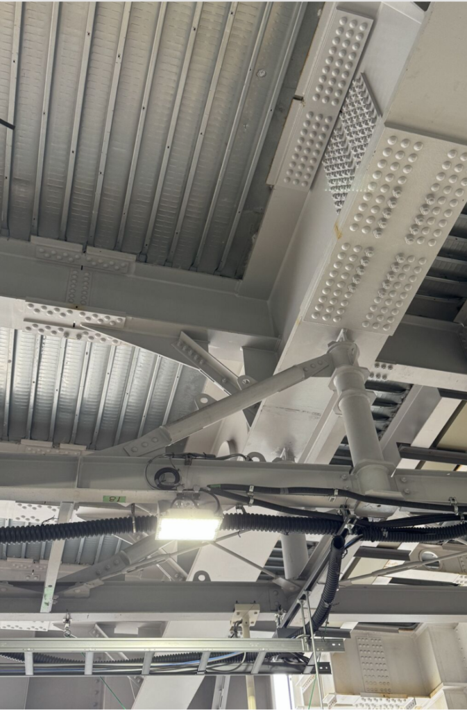
The photo above, taken looking up at the elevated steelwork of Shibuya Station in Tokyo, is a one-frame history of steel construction. Dome-headed rivets, high-strength bolted splices, welded gussets, and retrofit bracing all share the same few square meters of structure — and every train that rolls overhead loads all of them together. This post reads the connections in the photo and then asks the question that matters most in Tokyo: how does a century-old steel viaduct resist earthquakes?
1. Reading the Steelwork
The Rivet Fields
The most striking features in the photo are the dense rectangular arrays of dome-headed fasteners on the girder webs and flange cover plates. These are hot-driven rivets — the connection technology of Japanese railway construction from the early 1900s through roughly the 1950s. Portions of the elevated railway structure through central Tokyo date to the early decades of the twentieth century, when the Yamanote Line corridor was built out on steel and brick viaducts.
A hot rivet is installed glowing, and as it cools it shrinks axially, clamping the plates together. The result behaves partly like a friction connection and partly like a bearing connection: modest, variable clamping force, with the shank bearing against the hole once slip occurs. The dense patterns are dictated by the low capacity of each fastener — where a modern connection might use a handful of high-strength bolts, a riveted splice needs dozens of rivets, arranged in the neat rows and staggered grids visible in the photo.
Also characteristic: built-up members. Before wide-flange rolling and welding matured, girders were assembled from plates and angles — web plates, angle flanges, cover plates, and stiffeners — all riveted. Every plate edge in the photo that carries its own row of rivets is telling you the member was assembled, not rolled.
The Bolted and Welded Generations
Interleaved with the riveted work are flat splice plates with hexagonal-headed fasteners — high-strength friction-grip (HSFG) bolts — and cleanly welded gusset and bracket details. These mark later repair, strengthening, and reconstruction campaigns. A friction-grip bolt is tensioned to a controlled preload so that service loads transfer by friction between the faying surfaces with no slip at all:
where \( \mu \) is the slip coefficient of the faying surfaces, \( n \) the number of slip planes, and \( T_b \) the bolt pretension. Compared to rivets, the preload is higher, controlled, and inspectable — which is why bolting displaced riveting worldwide by the 1960s. For a railway structure, the no-slip behavior also matters for fatigue: a connection that never slips never frets, and the millions of stress cycles from train passages are carried across stable friction interfaces rather than working shanks.
The Diagonal Bracing and the Pipe Member
The diagonal members tying the girder system together laterally — and the stout tubular element at the center-right of the frame — are where the seismic story begins. Lateral bracing on a rail viaduct serves everyday duties (wind, nosing and hunting loads from the trains, lateral distribution between girders), but the heavier diagonals with generous multi-bolt gussets have the look of later strengthening: members proportioned not for wind, but for earthquake.
2. The Seismic Problem for an Old Steel Viaduct
Tokyo’s elevated railways must satisfy a brutal requirement set: support running trains, survive the design earthquake, and do it all without ever closing. The seismic behavior of a structure like this involves four distinct concerns.
Ductility of the Steel Itself
Steel is the most forgiving seismic material we have — provided the connections let the members yield. A steel frame survives a major earthquake by dissipating energy hysteretically, and mild steel can sustain large cyclic plastic strains. The design intent, as in all capacity-based seismic design, is a hierarchy: fuse elements yield, everything else stays elastic. For braced steel viaducts, the braces and their end connections are the designated fuses.
Connections Under Cyclic Load
The 1995 Kobe (Hyogoken-Nanbu) earthquake was the defining stress test for Japanese steel construction, just as Northridge (1994) was for American practice. Both events revealed brittle fracture in welded moment connections — cracks initiating at weld roots and flange discontinuities that were assumed ductile. Japanese practice responded with revised weld detailing, material toughness requirements, and inspection standards.
Riveted connections, interestingly, have a mixed but not disastrous seismic record. Their many small fasteners give them redundancy, and slip within the connection dissipates some energy. Their weaknesses are lower and less reliable clamping force, section loss at rivet holes, and — in old steel — parent material with lower fracture toughness and higher variability than modern grades. Assessment of a riveted structure is therefore as much a materials problem as a structural one: century-old steel can be closer to wrought iron in its chemistry and toughness than to anything in a modern mill certificate.
Fatigue Interaction
Here is the aspect closest to this blog’s usual territory. A rail viaduct accumulates on the order of 108 loading cycles over a century of service. Fatigue cracks nucleate at rivet holes, at the ends of cover plates, and at stiffener terminations — the classic Category D/E details. An earthquake then applies a handful of very large stress reversals to a structure whose details may already carry high-cycle fatigue damage. The interaction runs both ways: pre-existing fatigue cracks are initiation sites for seismic fracture, and the large inelastic seismic cycles consume low-cycle fatigue life in a Coffin–Manson sense. A cumulative damage assessment of an old viaduct must account for both regimes on the same detail.
The Supports Below
Although the photo looks up at the steel, the governing seismic vulnerability of Japanese rail viaducts historically has been the supporting columns. Kobe’s most sobering images were collapsed reinforced concrete viaduct bents. The nationwide response — one of the largest seismic retrofit programs ever executed — wrapped tens of thousands of RC rail and highway columns in welded steel jackets to restore shear strength and confinement. Steel superstructure spans like the one photographed generally rode out Kobe well when their supports held; span unseating and bearing failures, not girder fracture, dominated the damage statistics. Modern practice adds unseating-prevention devices (cable restrainers, seat extenders) and, on new construction, seismic isolation bearings.
3. Japan’s Seismic Code Arc
The structure in the photo has lived through the entire history of seismic engineering. The 1923 Great Kanto earthquake — which devastated Tokyo and Yokohama — produced Japan’s first seismic design coefficient (a static lateral force of roughly 10% of gravity) in 1924, among the first seismic provisions anywhere. Successive revisions culminated in the 1981 Shin-Taishin (new seismic) standard, a two-level design philosophy: essentially elastic response in moderate earthquakes, and controlled ductile response without collapse in rare major ones. After Kobe exposed the vulnerability of pre-1981 stock, retrofit of railway infrastructure became a national priority, and structures like Shibuya’s viaducts received successive rounds of strengthening — visible in the photo as the newer bolted bracing threaded among the rivets.
The deeper point for engineers outside Japan: the railway kept running throughout. Japanese practice has made an art of incremental strengthening under traffic — new members bolted alongside old, load paths shored and transferred one element at a time, all above a platform full of commuters. The photo is not a museum piece; it is a live structure carrying some of the world’s densest rail traffic while being continuously renewed. Shibuya Station itself has been undergoing one of Tokyo’s largest station redevelopment programs, with new towers and rebuilt platforms rising around and above steelwork like this.
4. Closing Thoughts
One photo, four generations of connection technology, and a complete seismic design philosophy. The rivet fields testify to the builders of a century ago; the friction-grip splices and heavy gussets record each subsequent decision to strengthen rather than replace; and the whole assembly reflects the central bargain of seismic steel design — let the material yield, keep the connections tougher than the members, and protect the load path from bearing to foundation. Structures are documents. This one is still being written.
Further Reading
- JSCE (Japan Society of Civil Engineers) reconnaissance reports on the 1995 Hyogoken-Nanbu earthquake — steel structure and railway viaduct damage.
- Kulak, Fisher, and Struik, Guide to Design Criteria for Bolted and Riveted Joints, 2nd ed. — the standard reference on rivet and HSFG bolt behavior.
- Fisher et al., fatigue detail categories for riveted and bolted built-up members (AASHTO/AREMA fatigue provisions).
- Railway Technical Research Institute (RTRI) design standards for railway structures — seismic design and retrofit of viaducts.
Related material: our September 2026 course series covers seismic analysis, shock response spectra, and fatigue damage accumulation. Free ebooks at vibrationdata.com/ebooks.
📌 Related Earthquake Engineering Knowledge Hub
This article is featured in our main Earthquake Engineering & Structural Dynamics Hub . Visit the hub to explore related articles on shock response spectra, time history analysis, seismic equipment qualification, and structural case studies.