Image https://empowering-technologies.com/metal-improvement/ultrasonic-impact-treatment/process/:
Introduction
Welded joints are the fatigue-critical details in most steel structures. The weld toe combines a sharp geometric stress concentration, tensile residual stresses approaching yield, and microscopic slag intrusions that act as pre-existing cracks. As a result, the fatigue strength of an as-welded joint is largely independent of the base metal strength — a frustrating reality for designers who specify high-strength steel and receive no fatigue benefit in return.
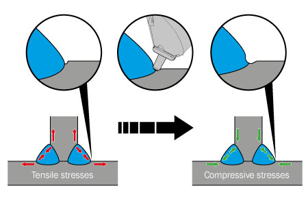
High Frequency Mechanical Impact (HFMI) treatment is a post-weld improvement method that attacks all three problems at the weld toe. A hardened cylindrical indenter, driven at high frequency, plastically deforms the weld toe region. The treatment is fast, portable, and now codified in International Institute of Welding (IIW) recommendations, making it one of the few improvement techniques with a formal design-by-analysis pathway.
The Process
An HFMI tool consists of one or more hardened steel pins, typically 3 mm in diameter with a tip radius of 1.5 to 3 mm, driven against the weld toe at impact frequencies well above those of conventional pneumatic hammer peening. The pins are excited either by an ultrasonic transducer (with a carrier frequency near 20 kHz producing impact rates on the order of 200 Hz and above) or by a high-frequency pneumatic mechanism. The operator traverses the tool along the weld toe at roughly 5 to 20 cm/min, leaving a smooth, uniform groove.
Several commercial implementations exist. All fall under the HFMI umbrella in the IIW recommendations:
| Designation | Common Name | Drive Mechanism |
|---|---|---|
| UIT | Ultrasonic Impact Treatment | Ultrasonic (magnetostrictive/piezoelectric) |
| UP / UPT | Ultrasonic Peening (Treatment) | Ultrasonic |
| HiFIT | High Frequency Impact Treatment | Pneumatic |
| PIT | Pneumatic Impact Treatment | Pneumatic |
Compared with traditional hammer or needle peening, HFMI tools transmit far less vibration to the operator and produce more consistent results, which is a significant ergonomic and quality-control advantage for production and field work.
Three Improvement Mechanisms
HFMI improves weld toe fatigue strength through three simultaneous mechanisms:
1. Compressive residual stress. The plastic deformation induces a compressive residual stress field at and below the treated surface, with magnitudes approaching the material yield strength and depths on the order of 1 to 1.5 mm. This compressive layer suppresses crack initiation and retards early crack growth by reducing the effective stress ratio at the toe.
2. Geometry improvement. The indenter increases the weld toe radius and removes the abrupt transition between weld metal and base plate, reducing the local stress concentration factor. The treatment also eliminates the shallow undercuts and slag intrusion line at the original toe.
3. Work hardening. The surface layer is cold worked, raising the local yield strength and further delaying crack initiation.
Because two of the three mechanisms (residual stress and work hardening) scale with material strength, HFMI finally lets high-strength steels deliver a fatigue benefit — the improvement increases with yield strength, in contrast to as-welded joints.
IIW Design Recommendations
The IIW recommendations by Marquis and Barsoum (2016) express the HFMI benefit as an increase in FAT class, where each class step corresponds to approximately a 12.5% increase in fatigue strength at \( 2 \times 10^6 \) cycles. The number of class steps depends on the specified minimum yield strength \( f_y \):
| Yield Strength \( f_y \) (MPa) | FAT Class Increase | Approximate Strength Factor |
|---|---|---|
| 235 < \( f_y \) ≤ 355 | 4 classes | 1.6 |
| 355 < \( f_y \) ≤ 550 | 5 classes | 1.8 |
| 550 < \( f_y \) ≤ 750 | 6 classes | 2.0 |
| 750 < \( f_y \) ≤ 950 | 7 classes | 2.3 |
| \( f_y \) > 950 | 8 classes | 2.6 |
The strength factor follows from compounding the class steps:
\[ \text{Improvement factor} = (1.125)^{k} \]where \( k \) is the number of FAT class increases.
Equally important, the recommended S-N slope changes from \( m = 3 \) (as-welded) to \( m = 5 \) (HFMI-treated), with a knee point at \( 1 \times 10^7 \) cycles. The characteristic design curve takes the usual form
\[ N = \frac{C}{\Delta \sigma^{m}} , \qquad m = 5 \]The shallower slope reflects the initiation-dominated behavior of the treated toe: at low stress ranges the compressive residual stress field is highly effective, while at high stress ranges local plasticity begins to relax it.
Design Example
Consider a transverse non-load-carrying stiffener on a plate of S690 steel ( \( f_y = 690 \) MPa). The as-welded nominal-stress detail category is FAT 80.
With 550 < \( f_y \) ≤ 750, the HFMI benefit is six FAT classes. Stepping through the standard IIW class sequence:
\[ 80 \rightarrow 90 \rightarrow 100 \rightarrow 112 \rightarrow 125 \rightarrow 140 \rightarrow 160 \]The treated detail is designed as FAT 160 with slope \( m = 5 \). At a constant-amplitude stress range of 200 MPa, the as-welded characteristic life is
\[ N_{aw} = 2 \times 10^{6} \left( \frac{80}{200} \right)^{3} \approx 1.3 \times 10^{5} \ \text{cycles} \]while the HFMI-treated life is
\[ N_{HFMI} = 2 \times 10^{6} \left( \frac{160}{200} \right)^{5} \approx 6.6 \times 10^{5} \ \text{cycles} \]a five-fold life extension at this stress level, with far larger ratios at lower stress ranges where the slope difference dominates.
Limitations and Penalties
The improvement relies on the stability of the compressive residual stress field, so the IIW recommendations impose several restrictions:
Stress ratio. The full benefit applies for \( R \le 0.15 \). As \( R \) increases, the guideline removes FAT classes in successive one-class penalties, and no improvement is claimed above approximately \( R = 0.52 \). High tensile mean stress works directly against the induced compressive field.
Maximum stress. Large tensile or compressive overloads can relax the residual stresses. The recommendations limit the maximum nominal stress and stress range relative to yield (on the order of 80% and 90% of \( f_y \), respectively) for the improvement to remain valid.
Variable amplitude loading. Spectrum loading with occasional overloads is the practical concern for bridges, cranes, and offshore structures. Rainflow cycle counting with explicit mean-stress bookkeeping becomes essential for treated details, since HFMI joints are considerably more mean-stress sensitive than as-welded joints, where high tensile residual stress renders the applied \( R \) ratio nearly irrelevant.
Validity range. The recommendations cover plate thicknesses of roughly 5 to 50 mm and yield strengths of 235 to 960 MPa. Thickness correction still applies for thick plates.
Failure location shift. A well-treated toe may simply move the critical location: root cracking in partial-penetration welds, or cracking from internal defects, is not improved by any toe treatment. HFMI is only appropriate for details governed by toe failure.
Quality Control
The treatment is only as good as its execution. Accepted quality criteria include a continuous, uniform, shiny groove along the entire weld toe with no visible remnant of the original toe line; a groove depth of approximately 0.2 to 0.6 mm; and a groove width consistent with the indenter geometry, typically 3 to 6 mm. Insufficient depth leaves the original toe defects intact, while excessive depth can fold material over and create laps. Simple depth gauges, visual standards, and operator training records form the basis of production QC.
Applications
HFMI has been applied to highway and railway bridges (both new construction and life extension of existing structures), ship and offshore structures, mobile cranes, and mining equipment. The retrofit case is particularly attractive: treating an existing weld toe that has not yet initiated a crack effectively resets much of the fatigue damage clock at that detail, and field treatment requires only a portable tool and access to the toe.
Closing Thoughts
HFMI is one of the rare fatigue improvement methods that combines a large, quantified benefit with a formal design framework and practical field deployment. Its greatest value appears in high-strength steel structures, where it recovers the fatigue performance that welding otherwise throws away. The caveats — mean stress sensitivity, overload relaxation, and disciplined quality control — are manageable with sound spectral fatigue analysis and inspection practice.
References
1. G. Marquis and Z. Barsoum, IIW Recommendations for the HFMI Treatment for Improving the Fatigue Strength of Welded Joints, Springer, 2016.
2. P.J. Haagensen and S.J. Maddox, IIW Recommendations on Methods for Improving the Fatigue Strength of Welded Joints, IIW-2142-10, Woodhead Publishing, 2013.
3. H.C. Yildirim and G.B. Marquis, “Fatigue Strength Improvement Factors for High Strength Steel Welded Joints Treated by High Frequency Mechanical Impact,” International Journal of Fatigue, Vol. 44, 2012.
4. A. Hobbacher, Recommendations for Fatigue Design of Welded Joints and Components, IIW-2259-15, Springer, 2016.
Looking for a deep dive on this topic? Explore our comprehensive guide and resource collection on the Residual Stress & Structural Integrity Hub.