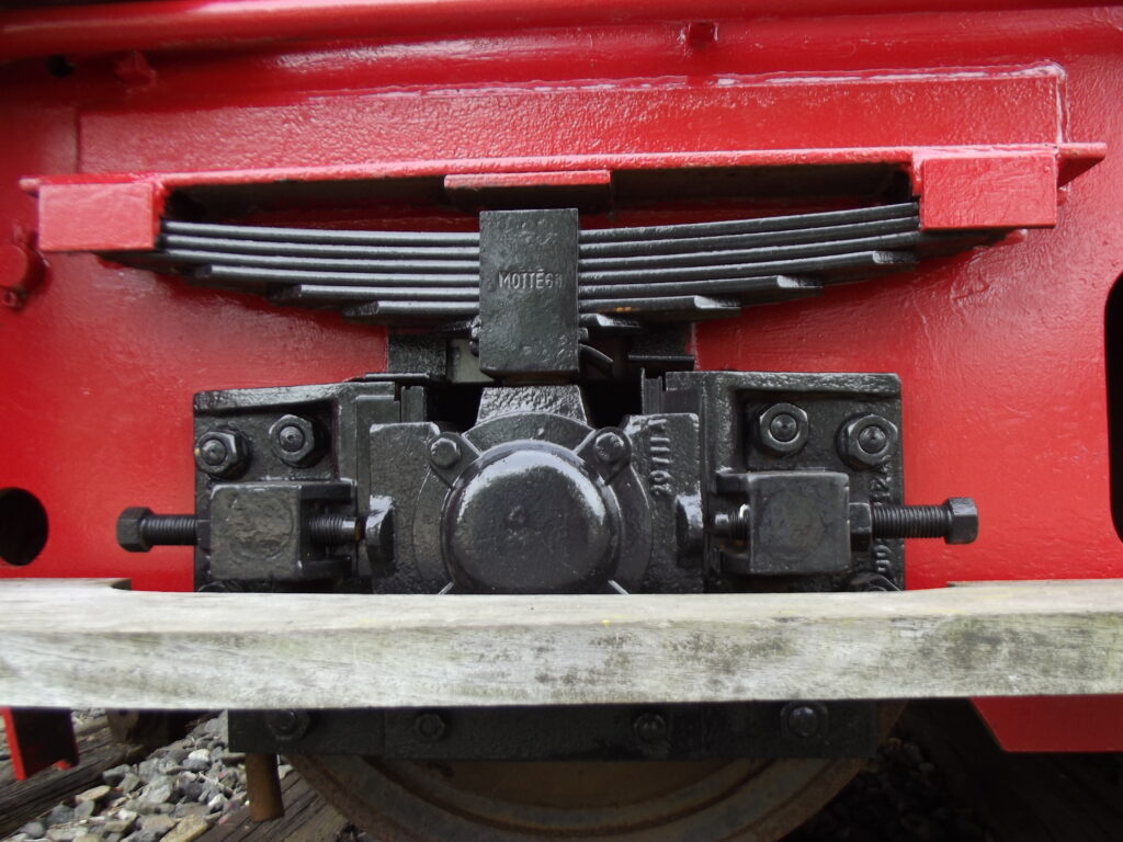
Anatomy of a Railway Leaf Spring: Axlebox-Mounted Primary Suspension
Photo credit: Wikimedia Commons, “Leaf spring on a train.jpg”, showing the primary suspension of a piece of German rolling stock.
The photo below is one of the clearest close-up views of a European-style axlebox-mounted leaf spring you’re likely to find — a good excuse to walk through the structural mechanics of this deceptively simple component, which has been the primary suspension medium for railway vehicles for close to 200 years.
1. What’s Actually in the Photo
This is the primary suspension of a two-axle wagon or coach, photographed head-on looking along the axle centerline. Working from the top down:
- The underframe/headstock (painted red) carries two spring shoes, visible as the slotted brackets at each end of the spring. The spring’s ends sit in these shoes rather than hanging from swinging links.
- The semi-elliptic leaf spring itself — a stack of roughly seven to eight graduated steel leaves, curved into a shallow arc, clamped at center by a spring band or buckle.
- The spring band is stamped “MOTTE 68,” almost certainly a manufacturer’s mark and either a batch code or a 1968 production date — the kind of small forensic detail that’s easy to miss but useful for dating and provenance work on preserved rolling stock.
- The axlebox (the black cast housing below the spring, with the circular access port on its face) rides directly beneath the spring’s center, captured vertically by the spring load and restrained fore-aft and laterally by axle guides (hornblocks) machined into the underframe — the vertical slots visible on either side of the axlebox casting.
- The two threaded rods running horizontally through small blocks on either side are most likely axlebox retaining/guide rods or safety straps, preventing the axlebox from dropping out of its guides in the event of a spring failure.
This is architecturally different from the swinging-hanger arrangement I saw today on a Great Western Dean Single replica locomotive. There, the spring’s ends hang from pin-jointed links so the spring’s arc can flex freely without inducing bending at the eyes. Here, the spring’s ends sit in captive shoes and the center of the spring bears directly on the axlebox — a design common on European two-axle wagons and coaches, where the axlebox itself, sliding vertically in its guides, is effectively the only moving suspension element besides the spring.
2. Semi-Elliptic Spring Mechanics
A semi-elliptic leaf spring is, structurally, a curved cantilever beam of variable cross-section, built up from graduated flat plates rather than machined as one piece. Stacking graduated leaves lets the spring achieve a favorable stress distribution along its length using simple flat stock, rather than requiring a tapered single leaf, which would be far more expensive to produce and replace.
For a simply-supported semi-elliptic spring of length \( L \) (the effective span between the two end shoes) loaded at its center with force \( P \), the classic multi-leaf spring formulas are:
Bending stress at the center of the master leaf:
\[ \sigma = \frac{3 P L}{2 n b t^{2}} \]Spring rate (vertical stiffness):
\[ k = \frac{P}{\delta} = \frac{8 E n b t^{3}}{L^{3}} \]where \( n \) is the number of leaves, \( b \) is the leaf width, \( t \) is the leaf thickness, and \( E \) is the elastic modulus of the spring steel. These are the same graduated-leaf idealizations used in automotive leaf spring design; they assume the leaves are free to slide against one another at their interfaces, which is exactly what allows the spring to flex as a laminated stack rather than as a solid, much stiffer block.
That sliding is worth dwelling on, because it does double duty: it’s what makes the graduated-leaf construction work mechanically, and it’s also the spring’s only source of damping. Every time the vehicle body moves relative to the axle, the leaves slide slightly against each other, and Coulomb (dry) friction at those interfaces dissipates energy. There is no separate dashpot anywhere in this assembly — the spring is simultaneously the spring and the damper, a detail worth keeping in mind if you’re ever tempted to model this suspension with a simple linear spring-and-viscous-damper analog. The hysteresis loop this friction produces is closer to rectangular than elliptical, and its damping capacity \( \psi = \Delta W / W \) depends on amplitude rather than velocity — the same friction-damping behavior covered in my earlier post on structural damping mechanisms.
3. Why the Spring Sits on the Axlebox Instead of Hanging from Shackles
Both suspension architectures — hung-spring and axlebox-mounted — solve the same problem (isolate the vehicle body from track irregularities) but make different trade-offs:
- Hung/shackle-mounted springs (as on the Dean Single tender/driving springs) let the spring’s arc-length change freely as it deflects, which is important on a rigid locomotive frame where the axle position is fixed by the frame’s horn guides and the spring only needs to transmit load, not guide the axle.
- Axlebox-mounted springs, like the one photographed here, combine the suspension function with the axle-guiding function: the axlebox itself rides in the frame’s horn guides, and the spring both supports the load and allows the axlebox (and hence the axle) to move vertically within those guides. This is simpler and lighter for a two-axle wagon or coach, where there’s no separate bogie frame to carry the load between spring and axle.
The trade-off is ride quality and unsprung mass: a bogie-mounted vehicle with equalized, hung springs generally rides better at speed, which is why express passenger stock evolved toward bogies while simpler wagon stock retained the direct axlebox-spring arrangement for far longer — in many parts of Europe, essentially unchanged from the 19th century into the late 20th, consistent with the 1968 date plausibly stamped into this very spring.
4. A Small Provenance Detail
The “MOTTE 68” stamp is a nice illustration of how much metadata gets cast or forged directly into running gear. Spring manufacturers commonly stamped their name, part number, and a date or batch code into the central band, both for quality traceability and so a maintenance depot could identify a compatible replacement spring without disassembly. For anyone cataloguing or restoring historic rolling stock, these stampings are often the only surviving evidence of original manufacture, since paperwork rarely survives as long as the ironwork itself.
References
- Photo: Wikimedia Commons, “Leaf spring on a train.jpg” (German rolling stock).
- VibrationData blog, “Why Union Pacific Is Painting Its Rails White” — for related rail/thermal mechanics.
- VibrationData blog, leaf spring commentary on the GWR Dean Single replica “The Queen,” Windsor & Eton Central.
- Timoshenko, S., Strength of Materials, Part II: Advanced Theory and Problems, for graduated-leaf spring stress and deflection formulas.