By Tom Irvine | Marine Corrosion Series — Madeira, Portugal (ISO 9223 Category C5)
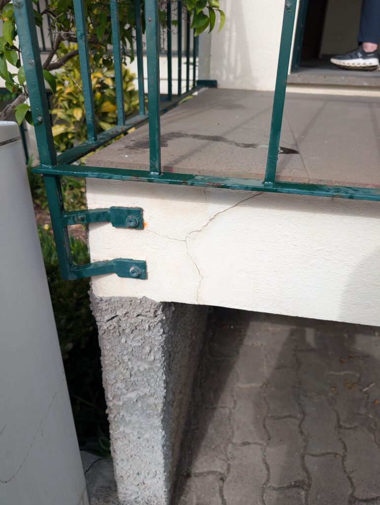
The photograph below was taken in Funchal, Madeira on 4 July 2026. It shows the corner bracket connection of a painted mild steel railing to a rendered concrete fascia on a coastal balcony. At first glance it appears to be a routine maintenance issue. On closer inspection, it is a textbook case of corrosion-induced concrete cracking — a failure mode that costs the global infrastructure industry an estimated $2.5 trillion annually and is responsible for premature structural retirement of bridges, parking garages, marine platforms, and building facades worldwide.
Three distinct degradation mechanisms are visible simultaneously in this single image:
- Orange rust weeping at the upper bracket bolt — iron oxide leaching from a corroding fastener through the render surface
- Diagonal cracking in the rendered fascia, propagating from the bolt anchor point — driven by the volumetric expansion of corrosion product within the confined bolt hole
- Paint breakdown on the mild steel railing — surface oxidation and delamination consistent with sustained C5 salt-laden atmospheric exposure
This post examines the mechanics of each mechanism, quantifies the expansion pressure responsible for the cracking, and presents the mitigation strategies that could have prevented this damage entirely.
1. The Electrochemical Foundation
Corrosion of iron in a marine environment is an electrochemical process driven by the oxygen concentration cell and galvanic coupling. The anodic and cathodic half-reactions are:
Anodic (oxidation — metal loss):
\[ \text{Fe} \rightarrow \text{Fe}^{2+} + 2e^- \]
Cathodic (reduction — oxygen consumption):
\[ \frac{1}{2}\text{O}_2 + \text{H}_2\text{O} + 2e^- \rightarrow 2\text{OH}^- \]
Secondary oxidation:
\[ 4\text{Fe}^{2+} + \text{O}_2 + 8\text{OH}^- \rightarrow 4\text{FeOOH} + 4e^- \]
The hydrated iron oxyhydroxide products — goethite (\(\alpha\)-FeOOH), lepidocrocite (\(\gamma\)-FeOOH), and amorphous ferrihydrite (Fe(OH)\(_3\)) — are the orange-brown compounds visible weeping from the bolt hole. Their formation is thermodynamically favored in the presence of dissolved chloride ions, which act as catalysts, breaking down passive oxide films and dramatically accelerating the anodic dissolution rate.
In a C5 coastal environment such as Madeira, airborne chloride deposition rates can reach 300–1000 mg/m²/day. Chloride ions migrate through render microcracks and the bolt-hole annulus, reaching the steel fastener surface within months to a few years of installation — especially if sealant was absent or degraded.
2. Volumetric Expansion: The Wedging Mechanism
The fundamental driver of the cracking visible in the photograph is the density mismatch between metallic iron and its corrosion products. Iron has a density of 7.87 g/cm³. The rust phases that form in service are far less dense:
| Compound | Formula | Density (g/cm³) | Molar Volume (cm³/mol) | Volume Ratio vs Fe |
|---|---|---|---|---|
| Iron | Fe | 7.87 | 7.09 | 1.00 |
| Magnetite | Fe₃O₄ | 5.18 | 44.7 | 2.10 |
| Hematite | Fe₂O₃ | 5.26 | 30.4 | 2.14 |
| Goethite | α-FeOOH | 4.26 | 20.8 | 2.94 |
| Lepidocrocite | γ-FeOOH | 4.09 | 21.7 | 3.06 |
| Ferrihydrite | Fe(OH)₃ | 3.80 | 28.1 | ~3.96 |
When the bolt corrodes within its confined hole, the growing rust product has nowhere to go. The render and concrete surrounding the bolt hole resist the expansion, generating internal pressure. This is the wedging mechanism — analogous to water freezing in a rock fissure, but operating continuously over months and years rather than cyclically with temperature.
Expansion Pressure Estimate
The expansion pressure \( p \) generated by constrained rust growth can be estimated using a thick-walled cylinder analogy. If the volumetric strain of the corrosion product is \( \varepsilon_v \), and the surrounding material has Young’s modulus \( E_c \) and Poisson’s ratio \( \nu \), the expansion pressure is approximately:
\[ p \approx \frac{E_c \, \varepsilon_v}{2(1-\nu)} \]
For a typical render/mortar with \( E_c \approx 10\text{ GPa} \) and \( \nu = 0.2 \), and a volumetric strain \( \varepsilon_v \approx 2 \) (a factor-of-3 volume increase implies \( \varepsilon_v \sim 2 \)), the theoretical pressure is enormous — on the order of 10 GPa — far exceeding any real material strength. In practice, the expansion pressure is limited by the cracking and creep of the surrounding concrete, but values of 4–40 MPa have been measured experimentally in reinforcement corrosion studies, far exceeding the tensile strength of concrete or render (typically 2–5 MPa).
Hoop Stress in the Surrounding Render
Treating the bolt hole as the inner radius of a thick-walled cylinder, the hoop (circumferential) stress in the surrounding render at radius \( r \) is:
\[ \sigma_\theta(r) = \frac{p \, r_i^2}{r_o^2 – r_i^2} \left(1 + \frac{r_o^2}{r^2}\right) \]
where \( r_i \) is the bolt hole radius, \( r_o \) is the outer cover radius, and \( p \) is the expansion pressure. The maximum hoop stress occurs at the inner surface (\( r = r_i \)):
\[ \sigma_{\theta,max} = \frac{2 \, p \, r_o^2}{r_o^2 – r_i^2} \]
For a 10 mm diameter bolt (\( r_i = 5\text{ mm} \)) with 20 mm of render cover (\( r_o = 25\text{ mm} \)) and an expansion pressure of only \( p = 5\text{ MPa} \):
\[ \sigma_{\theta,max} = \frac{2 \times 5 \times 25^2}{25^2 – 5^2} = \frac{3125}{600} \approx 5.2\text{ MPa} \]
This already exceeds the tensile strength of render. The crack in the photograph is the structural result — render splitting along the line of maximum hoop stress, propagating diagonally toward the free surface where the constraint is least.
3. Fracture Mechanics of the Propagating Crack
Once a crack initiates at the bolt hole, its subsequent propagation is governed by linear elastic fracture mechanics (LEFM). The stress intensity factor at the crack tip for a radial crack emanating from a circular hole is:
\[ K_I = \sigma_\theta \sqrt{\pi a} \cdot F\!\left(\frac{a}{r_i}\right) \]
where \( a \) is the crack length measured from the hole surface and \( F(a/r_i) \) is a geometry correction factor. Crack propagation occurs when \( K_I \geq K_{Ic} \), the fracture toughness of the render/concrete. For cement-based materials, \( K_{Ic} \approx 0.3\text{–}1.0\text{ MPa}\sqrt{\text{m}} \) — extremely low compared to metals — which is why even modest expansion pressures produce visible cracking relatively quickly.
The diagonal crack path visible in the photograph follows the principal tensile stress trajectory from the bolt hole toward the free corner of the fascia — the classic mode I opening crack path in a structure with a nearby free surface and a stress concentration at the anchor.
4. Galvanic Coupling at the Bracket
An additional accelerating factor visible in the photograph is the potential for galvanic corrosion at the bracket-bolt interface. If the bolts are carbon steel and the bracket is a different alloy (or vice versa), a galvanic cell is established when a conductive electrolyte (salt water or condensation) bridges the two metals. The more anodic metal (lower in the galvanic series) corrodes preferentially and rapidly.
Common problematic pairings in coastal construction:
| Anode (corrodes) | Cathode (protected) | EMF Difference |
|---|---|---|
| Carbon steel bolt | Stainless steel bracket | ~0.5 V |
| Carbon steel bolt | Copper flashing | ~0.6 V |
| Zinc-plated bolt | Carbon steel bracket | ~0.2 V (Zn sacrificial — intended) |
| Aluminum bracket | Carbon steel bolt | ~0.4 V |
The orange staining at the upper bolt in the photograph is consistent with a carbon steel fastener acting as the anode — corroding rapidly while the bracket (the larger cathodic area) is protected. The large cathode-to-anode area ratio accelerates the anodic dissolution rate by concentrating the cathodic current onto the small bolt cross-section.
5. What Could Have Been Done: Mitigation Strategies
This failure was entirely preventable. The following mitigation hierarchy addresses the problem at each level — material selection, design detailing, protective treatment, and monitoring.
5.1 Material Selection
Stainless steel fasteners (A4-80 / 316L grade) should have been specified for all bolts and anchors in this C5 environment. Type 316L contains 2–3% molybdenum, which dramatically improves pitting and crevice corrosion resistance in chloride environments by raising the critical pitting potential. The cost premium over carbon steel fasteners is typically 3–5×, but the lifecycle cost saving is 10–50× when premature replacement and structural repair are included.
Critically, all metals in contact should be from the same or closely matched galvanic series. Mixing carbon steel bolts with stainless brackets (or vice versa) in a conductive coastal environment guarantees accelerated galvanic corrosion of the more anodic component.
5.2 Isolation and Sealing
Even with correct material selection, the bolt-hole annulus provides a direct pathway for chloride-laden moisture to reach the fastener shank. Proper detailing requires:
- Non-conductive isolating sleeves (nylon or HDPE) around bolts passing through concrete or render, breaking the galvanic circuit
- Polyurethane or polysulfide sealant at the bolt head–render interface, preventing water ingress into the annular gap
- Stainless steel or EPDM washers to distribute bearing load and seal the entry point
- Cap seals or decorative covers over exposed bolt heads to eliminate moisture pooling in the bolt recess
5.3 Corrosion-Resistant Coatings
For the mild steel railing itself, a properly specified coating system for C5 marine environments per ISO 12944 consists of:
- Surface preparation: Sa 2½ blast cleaning (near-white metal) per ISO 8501-1 — the single most important factor in coating durability
- Primer: Zinc-rich epoxy primer (≥ 80% Zn by weight in dry film) — 60–80 μm DFT. The zinc provides cathodic protection of the steel even if the topcoat is breached.
- Intermediate coat: High-build epoxy — 100–150 μm DFT
- Topcoat: Polyurethane or fluoropolymer — 50–80 μm DFT for UV and weathering resistance
- Total DFT: ≥ 240 μm for C5 Marine per ISO 12944-5
The degraded paint visible in the photograph is consistent with an inadequate primer specification or insufficient surface preparation — paint applied over mill scale or light hand-tool cleaning rather than blast cleaning, producing early adhesion failure and underfilm corrosion.
5.4 Concrete Cover and Mix Design
For the rendered fascia, the crack resistance against bolt expansion is directly related to the cover thickness \( c \) over the anchor. Eurocode 2 (EN 1992) specifies minimum cover of 45 mm for XS3 (tidal/splash marine) exposure class. Increasing cover increases \( r_o \) in the hoop stress formula, reducing \(\sigma_{\theta,max}\) substantially.
Additionally, the render mix could have been specified with:
- Low water-cement ratio (w/c ≤ 0.40) to reduce porosity and chloride diffusivity
- Supplementary cementitious materials — silica fume or fly ash — which refine the pore structure and reduce chloride ingress rate by up to 80%
- Integral crystalline waterproofing admixtures (e.g. Xypex, Kryton) which self-seal microcracks by precipitating calcium silicate hydrate crystals in the presence of moisture
- Fiber reinforcement (polypropylene or steel microfibers) to arrest crack propagation by bridging across the crack faces, increasing the apparent fracture toughness \( K_{Ic} \)
Fiber-reinforced render increases \( K_{Ic} \) from ~0.4 MPa√m to ~1.5–2.5 MPa√m — a 4–6× improvement in crack arrest capability for the same expansion pressure.
5.5 Cathodic Protection
For existing structures where material upgrade is not feasible, impressed current cathodic protection (ICCP) or sacrificial anode cathodic protection (SACP) can be applied to halt ongoing corrosion. In SACP, zinc or aluminum alloy anodes are connected to the steel, preferentially corroding and supplying electrons that suppress the anodic reaction on the fastener.
The protection criterion per BS EN ISO 12696 is to shift the steel potential to between −770 mV and −1100 mV vs. Ag/AgCl/0.5M KCl reference electrode. Achieving this potential electrically forces the anodic dissolution reaction to stop — corrosion current drops to essentially zero.
5.6 Inspection and Monitoring
Had a routine maintenance inspection protocol been in place, the early-stage corrosion could have been detected and treated before structural cracking occurred. Effective monitoring tools include:
- Half-cell potential mapping (ASTM C876) — measures the electrochemical potential of embedded steel; values more negative than −350 mV vs. Cu/CuSO₄ indicate >90% probability of active corrosion
- Galvanostatic pulse technique — non-destructive measurement of instantaneous corrosion rate (icorr) in μA/cm²
- Infrared thermography — delaminated render shows thermal anomalies due to the air gap behind the crack
- Acoustic emission monitoring — crack propagation events generate stress waves detectable by surface-mounted piezoelectric sensors; a structural health monitoring (SHM) approach increasingly deployed on bridges and marine structures
- Visual inspection with crack gauges — inexpensive tell-tale gauges bonded across active cracks reveal whether propagation is ongoing
6. Repair Strategy for the Existing Damage
For the structure as photographed, a remediation sequence would include:
- Remove corroded fasteners — cut out bolts and grind the anchor zone to remove all rust product
- Chase out the crack — saw-cut or grind the crack to a 5–10 mm wide, square-edged channel to provide a bondable substrate
- Apply corrosion inhibitor — penetrating amino-alcohol or amine-based inhibitor (e.g. Sika FerroGard-903) to the exposed anchor zone and surrounding concrete by brush application
- Re-anchor with stainless steel chemical anchors — A4-316 stainless threaded rod with epoxy or cementitious anchor grout, with nylon isolation sleeve
- Seal bolt-head interface — polyurethane sealant, tooled flush
- Fill crack with flexible epoxy injection — low-viscosity epoxy resin injected under pressure to restore structural continuity and prevent further moisture ingress
- Re-render affected zone — polymer-modified cementitious render with silica fume, feathered to match existing surface
- Apply penetrating silane/siloxane sealer to the entire fascia — 40 mm penetration depth, reduces water absorption by >90% for 10–15 year service life
- Re-coat the railing — blast clean to Sa 2½, apply full ISO 12944 C5 coating system as described above
7. Structural Dynamics Perspective
From a vibration standpoint, the cracked render fascia and corroded bracket connection represent a degraded boundary condition for the railing structure. A railing that was designed as a fixed-base cantilever now has a partially compliant base due to:
- Reduced bolt shank cross-section from corrosion (section loss reduces shear capacity)
- Crack in the concrete reducing the effective embedment depth and load transfer area
- Loss of bearing contact between bolt head/washer and render surface
The natural frequency of the railing as a cantilever beam is:
\[ f_n = \frac{\lambda^2}{2\pi L^2} \sqrt{\frac{EI}{\rho A}} \]
where \( \lambda = 1.875 \) for the first mode of a fixed-free beam. As the base stiffness \( k_{base} \) degrades from the ideal fixed condition toward a pinned or free condition, \( f_n \) drops. This frequency shift is measurable and forms the basis of vibration-based structural health monitoring — a tap test or ambient vibration measurement compared against the as-built baseline reveals the extent of connection degradation.
In a coastal environment, wind-induced vortex shedding also excites the railing at a frequency:
\[ f_s = \frac{S_t \, U}{D} \]
where \( S_t \approx 0.2 \) is the Strouhal number for a circular or rectangular cross-section, \( U \) is the wind velocity, and \( D \) is the railing bar diameter. If \( f_s \) approaches \( f_n \), lock-in occurs and resonant oscillation amplifies the stress at the already-compromised bracket base — potentially accelerating crack propagation from the quasi-static wedging regime into fatigue-driven growth.
Summary
A single coastal bracket connection, photographed on a morning walk in Madeira, contains the full narrative of corrosion-induced structural degradation:
- Electrochemical dissolution driven by chloride catalysis in a C5 marine environment
- Volumetric expansion of rust products (up to 4× the parent iron volume) generating internal wedging pressure
- Hoop stress in the surrounding render exceeding its tensile strength, initiating diagonal cracking from the bolt hole
- Galvanic acceleration from dissimilar metal contact at the bracket interface
- Degraded boundary condition reducing railing natural frequency and potentially enabling wind-induced resonance
All of this was preventable with the correct material specification (A4-316 stainless fasteners), proper sealant detailing at the bolt–render interface, an ISO 12944 C5-compliant coating system on the railing, and a routine half-cell potential inspection programme. The cost of prevention would have been a small fraction of the current remediation cost — a ratio that repeats itself across infrastructure worldwide.
< Madeira lies within a low-to-moderate seismic hazard zone (design PGA ~0.05–0.10g per Eurocode 8). While absolute seismic forces on a railing bracket are modest, the pre-existing crack and corroded fastener represent a degraded connection whose remaining capacity margin may be insufficient for the combined static + seismic demand. Seismic events also impose cyclic lateral loading — potentially propagating the existing crack from stable to dynamic fracture at stress intensities well below the undamaged K Ic of the render. This is an additional argument for immediate repair rather than deferred maintenance.
Part of the VibrationData Marine Corrosion Series — Madeira, Portugal, July 2026. Related posts: ISO 9223 Category C5 Hardware Failures; Stress Corrosion Cracking and Fracture Mechanics; Aluminum Fuselage Corrosion Fatigue.
References and further reading at vibrationdata.com.