This is the second post in a series on marine corrosion observed at coastal infrastructure in Madeira, Portugal, July 2026. Part 1 covered a severely corroded bolt and nut at a seaside retaining wall. Here we examine two additional specimens from the same location: a hollow structural steel post that has corroded from the inside out, and a painted tubular steel railing with a through-wall perforation. Together the three photographs illustrate nearly every major atmospheric corrosion failure mode in a single coastal environment.
Introduction
Madeira’s Atlantic coastline sits firmly in ISO 9223 corrosivity Category C5 — the most aggressive atmospheric classification — driven by high chloride deposition from ocean spray, persistent high relative humidity, cyclic wetting and drying, and elevated temperatures. In Part 1 we saw what these conditions do to an unprotected carbon steel fastener over years of exposure. In this post, the subjects are structural steel members: a hollow section post and a painted tube railing, both at or beyond the end of their serviceable life.
What makes these two specimens instructive is that both had some form of corrosion protection applied at the time of installation — paint on the tube, and a welded cap on the hollow post. Both protections have failed, and the consequences are now structural rather than merely cosmetic.
Image 1: Hollow Steel Section — Internal Entrapment Corrosion
Observation and Failure Mode
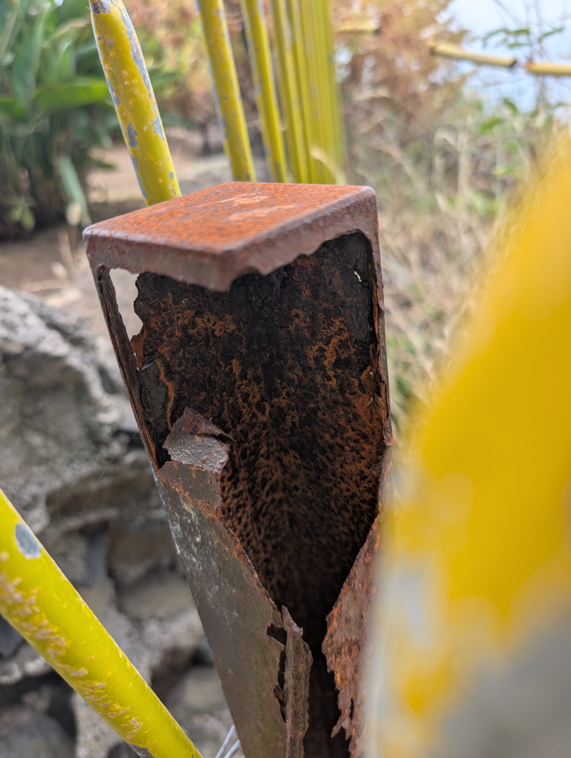
This is a carbon steel hollow structural section (HSS), most likely a square tube fence post or railing upright. The structural condition is terminal. The tube walls have split longitudinally and delaminated outward, driven by the volumetric expansion of corrosion products accumulating inside the section. The top cap — a flat plate welded or pressed onto the tube end — has retained its geometry but is itself heavily rusted, and it is the primary culprit: it created an enclosed interior space that trapped water and never allowed it to drain or evaporate.
The rust morphology visible in the photograph is diagnostic. Moving from the deepest interior outward, the color sequence is:
- Black (magnetite, Fe₃O₄): Forms under oxygen-depleted conditions in the deep interior of the tube, where dissolved oxygen is consumed and cannot be replenished. Magnetite is relatively dense and stable, but its presence indicates a persistently wet, anaerobic environment.
- Dark brown (goethite, α-FeOOH): The most thermodynamically stable iron oxyhydroxide, forming in moderate humidity cycling conditions. Goethite is the dominant long-term rust phase in atmospheric corrosion.
- Bright orange (lepidocrocite, γ-FeOOH): Forms rapidly during wet phases; less stable than goethite. Its vivid orange color at the outer surface indicates active, ongoing corrosion — this is fresh rust forming in the most recent wet cycle.
This layered phase sequence — magnetite → goethite → lepidocrocite — is a signature of long-duration internal entrapment corrosion and is well documented in the literature on weathering steel and enclosed structural sections [Evans, 1960; Stratmann and Müller, 1994].
The Mechanism: Why Hollow Sections Are Especially Vulnerable
Hollow sections in marine environments present a worst-case corrosion scenario when improperly sealed. Water enters through:
- Incomplete or pinholed cap welds
- Any unsealed opening at the base (drain holes omitted, or base plate gaps)
- Condensation cycling — warm days drive moisture into the interior; cool nights condense it on interior walls
- Capillary action at base embedments in concrete or soil
Once water is trapped inside, the electrochemical cell dynamics shift dramatically compared to an open surface. The interior becomes oxygen-depleted as the cathodic reduction reaction consumes dissolved O₂ faster than it can diffuse in. This establishes a differential aeration cell: the interior surface becomes strongly anodic (actively dissolving), while any area with better oxygen access — such as a small gap in the cap weld — becomes cathodic. The geometry concentrates corrosion on the interior walls precisely where it cannot be seen or treated.
Compounding this, the corrosion products that form are voluminous. The molar volume of common iron oxides relative to metallic iron:
- Fe₂O₃ (hematite): ~2.1× the volume of iron
- Fe₃O₄ (magnetite): ~2.0×
- FeOOH (goethite/lepidocrocite): ~2.9–3.0×
- Fe(OH)₃ (ferrihydrite): ~3.5–4.0×
In a confined interior, this volumetric expansion generates internal pressure that the thin tube walls cannot resist. The result is exactly what Figure 1 shows: the walls split and peel outward, exposing the corroded interior. The structural wall thickness — perhaps originally 3–5 mm for a light fence post — has been reduced to flaking lamellae with no remaining tensile or compressive capacity.
Structural Assessment
This post has failed structurally. The net cross-sectional area has been reduced by an estimated 60–80%. Under lateral loading from wind or human contact, the remaining material has no capacity to develop meaningful bending resistance. ISO 4628-3 rust grade: Ri5 (>40% of surface showing visible rust breakdown). Condition state: condemnable.
Image 2: Yellow-Painted Steel Tube — Through-Wall Perforation by Pitting
Observation and Failure Mode
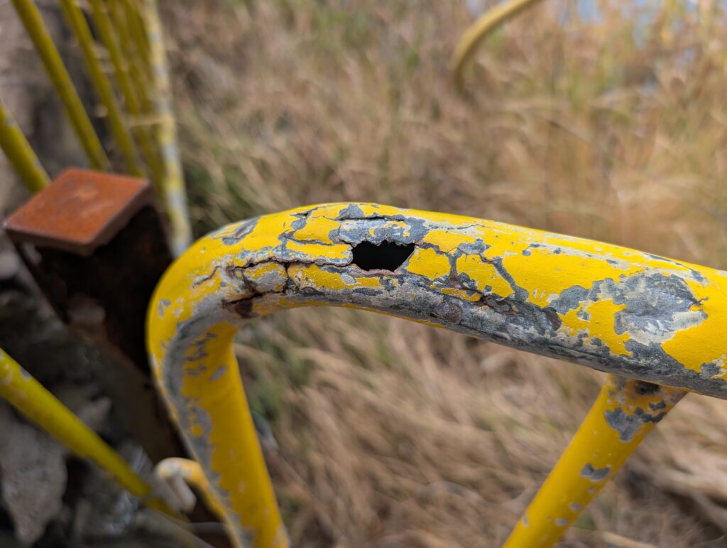
This painted carbon steel tube — a handrail or pedestrian safety barrier — exhibits a through-wall corrosion perforation at what appears to be the lowest point of a curved section. The black void is a complete breach: the tube wall has been consumed entirely at this location. This is the end state of a pitting corrosion process that initiated at a paint holiday and progressed inward until there was no remaining wall thickness.
The paint failure is itself instructive. The yellow topcoat over a gray primer (likely a zinc phosphate or alkyd primer, now fully degraded) shows all stages of marine paint degradation simultaneously:
- Cracking and crazing — UV degradation and thermal cycling have embrittled the topcoat, creating a network of cracks that admit moisture
- Osmotic blistering — water vapor diffuses through the film and condenses at the metal/paint interface, dissolving soluble salts and creating osmotic pressure that lifts the film
- Underfilm corrosion — rust forms beneath the intact paint, visible as the brown discoloration at the edges of delaminated zones
- Adhesion loss and flaking — the delaminated paint peels away, exposing bare steel to direct atmospheric attack
- Perforation — concentrated pitting at the exposed site penetrates the full wall thickness
The Pitting Mechanism
Pitting at a paint holiday in a chloride environment follows a well-understood sequence. When the paint film is breached, a small area of bare steel is exposed to the electrolyte (salt-laden condensate or rain). An oxygen concentration cell forms between the pit interior (low O₂, anodic) and the surrounding painted surface (relatively high O₂ access, cathodic). The large cathodic area relative to the small anodic pit area concentrates the corrosion current on the pit, driving rapid depth-wise penetration rather than uniform surface loss.
Within the pit, hydrolysis of dissolved Fe²⁺ lowers the local pH:
Fe²⁺ + 2H₂O → Fe(OH)₂ + 2H⁺
The resulting acidic, chloride-enriched pit chemistry is autocatalytic — it inhibits re-passivation and sustains active dissolution even if the external environment becomes more benign. This is why pitting is so insidious: once initiated in a marine environment, it tends to propagate continuously until perforation or fracture.
The location of the perforation at the lowest point of the curved section is not coincidental. Bends in tubing create:
- Water pooling on the outer radius during rain events
- Residual tensile stress from cold bending on the outer fiber, which reduces the pitting initiation threshold
- Paint film thinning at the bend apex during application (brush and spray coatings deposit thinner films on curved convex surfaces)
All three factors converge at the outer radius of a tube bend to make it the most likely perforation site — which is exactly what Figure 2 shows.
Structural Assessment
A perforated handrail tube cannot develop the full hoop stress and wall shear capacity required for a safety barrier. European standard EN 13374 requires handrails to resist a minimum horizontal line load of 1.0 kN/m and a concentrated load of 1.25 kN at any point. The net section at the perforation location is insufficient for these demands. This railing should be taken out of service.
The Paint System Problem: Why Topcoat Alone Is Insufficient
Both specimens show the consequence of relying on a barrier coating without an adequate sacrificial undercoat. A paint system performs two fundamentally different corrosion protection functions:
Barrier protection — the topcoat physically excludes moisture and oxygen. This works only as long as the film is intact and adherent. Every scratch, holiday, and UV-induced crack is a breach that exposes bare steel. In a C5 marine environment, even a well-applied barrier coating system will develop holidays within 3–7 years without maintenance.
Sacrificial (cathodic) protection — a zinc-rich primer (containing >80% metallic zinc dust by dry film weight, per SSPC-Paint 20 / ISO 12944 Class H) provides galvanic protection at holidays. The zinc is anodic to iron and corrodes preferentially, just as a sacrificial anode does in an immersion system. The critical difference from a standard primer: the zinc particles must be in electrical contact with each other and with the steel substrate to form a continuous galvanic network.
The gray primer visible beneath the yellow topcoat in Figure 2 is not a zinc-rich primer — its appearance and the rapid sub-film corrosion are inconsistent with an active zinc layer. It appears to be a zinc phosphate or alkyd primer that provides only mild barrier enhancement and no sacrificial capacity. When the topcoat failed, there was no galvanic reserve to slow the pitting.
The correct paint system specification for carbon steel in ISO C5-M (marine) environments per ISO 12944-5 is a minimum of:
- Surface preparation: Sa 2½ abrasive blast per ISO 8501-1 (near-white metal) — a clean, profiled surface is the single most important factor in coating durability
- Primer: Two-component epoxy zinc-rich, 60–80 µm DFT (dry film thickness)
- Intermediate coat: Two-component epoxy, 100–150 µm DFT
- Topcoat: Two-component polyurethane or fluoropolymer, 50–80 µm DFT
- Total DFT: 210–310 µm minimum
- Expected maintenance interval: 10–15 years in C5-M with annual inspection
A single-coat system of alkyd primer plus decorative topcoat — which appears to be what was applied here — has a realistic service life of 3–5 years in a C5 environment before maintenance painting is required. Without repainting, the system progresses to the failure state visible in Figure 2.
Comparison: All Three Specimens
| Feature | Bolt & Nut (Part 1) | Hollow Post (Fig. 1) | Yellow Tube (Fig. 2) |
|---|---|---|---|
| Form | Fastener (M-series carbon steel) | HSS square tube post | Circular tube railing |
| Initial protection | None | Welded top cap (partial) | Paint system (alkyd primer + topcoat) |
| Dominant mechanism | Uniform + pitting + crevice | Internal entrapment + differential aeration | Pitting under failed paint film |
| Rust phases visible | Lepidocrocite, goethite | Magnetite, goethite, lepidocrocite | Lepidocrocite at holiday sites |
| ISO 4628-3 rust grade | Ri5 | Ri5 | Ri4–Ri5 at failure site |
| Structural status | No function remaining | Failed — condemned | Perforated — unsafe |
| Primary lesson | Specify 316L stainless or HDG | Seal or fill hollow sections | Zinc-rich primer is non-negotiable in C5 |
Design and Maintenance Recommendations
Drawing from all three photographs, the following recommendations apply to coastal structural steel in ISO C5-M environments:
1. Avoid unsealed hollow sections. If HSS must be used, fully seal all openings by continuous weld, or specify closed-cell foam infill. Alternatively, provide drain holes at the lowest point of each member — a minimum 10 mm diameter hole per 300 mm of enclosed length, angled to drain freely. Consider solid bar stock or structural fiberglass (pultruded GRP) sections where strength requirements permit.
2. Specify zinc-rich primers, not zinc phosphate. The distinction matters enormously in C5 environments. Zinc-rich epoxy primer (SSPC-Paint 20 Level 1, ≥65% zinc by weight in dry film) provides active galvanic protection at coating holidays. Zinc phosphate primers are passive barrier enhancers only — adequate in C2–C3 environments, insufficient in C5.
3. Abrasive blast before painting. Surface preparation is the dominant variable in coating longevity. ISO Sa 2½ (near-white blast) is the minimum for C5-M. Brush-off blast (Sa 1) or hand-tool cleaning is not adequate regardless of paint system quality.
4. Inspect and maintain on a defined schedule. In C5 environments, first maintenance painting should be anticipated at 5–7 years from initial application even with a correctly specified system. Spot-prime and overcoat at first sign of rust breakthrough; do not wait for widespread failure.
5. Address bend zones specifically. Tube bends are high-risk sites for pitting initiation due to water pooling, stress concentration, and paint thinning. Specify additional stripe coating (brush application of primer to edges, welds, and bends before the full system is applied) to ensure adequate DFT at these locations.
6. Consider GRP or stainless alternatives for safety-critical members. For handrails and barriers that must retain structural capacity over a 20–30 year design life in a marine environment, carbon steel with paint is a high-maintenance choice. Pultruded glass-reinforced polymer (GRP) structural sections are corrosion-immune, require minimal maintenance, and are now available in standard structural shapes (tube, angle, channel, wide flange). 316L stainless steel tube is the standard alternative for marine handrails and has a proven service life exceeding 30 years in C5 conditions when properly specified.
Corrosion Fatigue: The Hidden Risk
Beyond immediate structural capacity, both specimens raise a corrosion fatigue concern. Coastal railings and barrier posts are subject to cyclic loading from wind buffeting, pedestrian contact, and wave-induced ground motion. The pitting visible in both images creates stress concentrations that dramatically reduce the fatigue life of the remaining material.
The stress intensity factor at a surface pit of depth a under remote stress σ is:
KI = F · σ · √(πa)
For a semi-circular surface pit, F ≈ 0.73. Even a shallow pit of depth a = 1 mm under a modest stress of 50 MPa gives KI ≈ 2.0 MPa√m — approaching the fatigue crack propagation threshold (ΔKth) for carbon steel in air of approximately 6–8 MPa√m. In a corrosive environment, ΔKth drops significantly — to as low as 2–4 MPa√m for steel in seawater — meaning fatigue cracks can propagate from even small pits under stresses well below the nominal design allowable.
This coupling of corrosion damage with fatigue crack initiation and propagation — corrosion fatigue — is why corroded structural members must not be assessed on residual static capacity alone. A member that still appears to carry static loads adequately may be accumulating fatigue damage at an accelerated rate from corrosion pits acting as crack initiators.
Conclusion
Three photographs from a single coastal walk in Madeira illustrate the full spectrum of atmospheric corrosion failure in structural carbon steel: unprotected fasteners consumed by uniform and crevice attack; a hollow section post destroyed from within by entrapment corrosion; and a painted tube railing perforated by pitting after its inadequate paint system failed. In each case the outcome was predictable and preventable.
The common thread is that ISO C5-M environments demand specification choices — alloy selection, paint system design, section geometry — that are materially different from what is adequate in mild inland environments. The cost of getting it right at design and installation is a small fraction of the cost of structural failure, safety incidents, and emergency replacement that these photographs represent.
Part 1 of this series is available here: Carbon Steel Marine Corrosion — Bolt and Nut Failure in Madeira.
References
- ISO 9223:2012, Corrosion of metals and alloys — Corrosivity of atmospheres — Classification, determination and estimation
- ISO 4628-3:2016, Paints and varnishes — Evaluation of degradation of coatings — Part 3: Assessment of degree of rusting
- ISO 12944-5:2019, Paints and varnishes — Corrosion protection of steel structures by protective paint systems — Part 5: Protective paint systems
- ISO 8501-1:2007, Preparation of steel substrates before application of paints and related products — Visual assessment of surface cleanliness
- SSPC-Paint 20, Zinc-Rich Primers (Type I — Inorganic and Type II — Organic), Society for Protective Coatings
- EN 13374:2013, Temporary edge protection systems — Product specification, test methods
- Evans, U.R., The Corrosion and Oxidation of Metals, Edward Arnold, London, 1960
- Stratmann, M. and Müller, J., “The mechanism of the oxygen reduction on rust-covered metal substrates,” Corrosion Science, 36(2), 327–359, 1994
- Melchers, R.E., “Long-term immersion corrosion of steels in seawater with elevated nutrient concentration,” Corrosion Science, 81, 2014
- Bardal, E., Corrosion and Protection, Springer, 2004
- Suresh, S., Fatigue of Materials, 2nd ed., Cambridge University Press, 1998 — Chapter 8: Corrosion Fatigue
Tom Irvine | VibrationData | blog.vibrationdata.com