Image reference: https://www.sciencedirect.com/science/article/abs/pii/S0020740323003296
Introduction
Classical fatigue analysis is built on stress. The stress-life (S-N) approach correlates nominal stress amplitude to cycles to failure; the strain-life ($\varepsilon$-N) approach handles the plasticity at notch roots through the Coffin-Manson equation; linear elastic fracture mechanics (LEFM) characterizes crack growth through the stress intensity factor $K$.
Each of these frameworks has served the engineering community well for decades, yet each carries inherent limitations when applied to the complex stress states found at notches, welds, and mixed-mode crack tips.
The strain energy density (SED) method offers an alternative that is physically appealing and practically powerful: rather than tracking a single stress or strain component, it uses the energy per unit volume stored elastically or dissipated plastically in the material as the fundamental damage parameter.
Because energy is a scalar, the SED approach handles multiaxial stress states, mixed fracture modes, and notch geometries in a unified framework that single-component stress or strain approaches cannot easily replicate.
This post traces the SED method from its theoretical roots in fracture mechanics through its application to notch fatigue and welded joint assessment, and discusses its practical implementation for engineering structural life prediction.
Strain Energy Density: The Fundamental Concept
The strain energy density $W$ at a point in a linear elastic body is the work done per unit volume by the stress field in deforming the material to its current state: $$W = \frac{1}{2} \sigma_{ij} \varepsilon_{ij}$$ For a uniaxial stress state this reduces to the familiar: $$W = \frac{\sigma^2}{2E}$$ where $\sigma$ is the stress and $E$ is Young’s modulus. For a general three-dimensional stress state with principal stresses $\sigma_1$, $\sigma_2$, $\sigma_3$: $$W = \frac{1}{2E} \left[ \sigma_1^2 + \sigma_2^2 + \sigma_3^2 – 2\nu(\sigma_1\sigma_2 + \sigma_2\sigma_3 + \sigma_1\sigma_3) \right]$$ This expression decomposes naturally into two physically distinct parts: $$W = W_v + W_d$$ where $W_v$ is the dilatational (volumetric) energy density associated with volume change under hydrostatic stress, and $W_d$ is the distortional energy density associated with shape change under deviatoric stress.
This decomposition is not merely mathematical convenience — it maps directly onto the two competing failure modes in engineering materials: brittle cleavage fracture driven by hydrostatic tension, and ductile shear failure driven by deviatoric stress.
The von Mises yield criterion, familiar to every structural engineer, is already a strain energy density criterion in disguise: it states that yielding occurs when the distortional energy density $W_d$ reaches a critical value equal to the distortional energy at yield in a uniaxial tension test.
Sih’s Strain Energy Density Factor: Fracture Mechanics Application
The first rigorous application of SED to fracture mechanics is due to George C. Sih of Lehigh University, whose landmark 1974 paper in the International Journal of Fracture established the Strain Energy Density Factor $S$ as a crack propagation criterion applicable to mixed-mode loading.
The S Factor
For a crack in a linear elastic body under combined Mode I (opening), Mode II (in-plane shear), and Mode III (anti-plane shear) loading, the near-tip stress field produces a strain energy density that varies with distance $r$ from the crack tip as: $$\frac{dW}{dV} = \frac{S}{r}$$ where the *lstrain energy density factor $S$ is a function of the stress intensity factors $K_I$, $K_{II}$, $K_{III}$ and the polar angle $\theta$ measured from the crack plane: $$S = a_{11}K_I^2 + 2a_{12}K_I K_{II} + a_{22}K_{II}^2 + a_{33}K_{III}^2$$ The coefficients $a_{11}$, $a_{12}$, $a_{22}$, $a_{33}$ are functions of $\theta$ and the elastic constants (Young’s modulus $E$, Poisson’s ratio $\nu$). For a pure Mode I crack under plane strain conditions: $$a_{11} = \frac{(1+\nu)(1-2\nu)}{2\pi E}$$ Sih’s criterion consists of two postulates that together determine both the direction of crack propagation and the load level at fracture:
> Postulate 1 (Direction of crack growth). The crack extends in the direction $\theta_0$ that minimizes $S$, i.e., the direction of minimum strain energy density. This is found from: > $$\frac{\partial S}{\partial \theta} = 0, \quad \frac{\partial^2 S}{\partial \theta^2} > 0$$ > Postulate 2 (Critical condition for fracture). Crack growth initiates when $S$ at $\theta = \theta_0$ reaches a critical material constant $S_{cr}$: $$S_{\min} = S_{cr}$$ The critical value $S_{cr}$ is a material property analogous to fracture toughness $K_{Ic}$ and can be determined from a standard fracture test. For pure Mode I under plane strain: $$S_{cr} = \frac{(1 – 2\nu)K_{Ic}^2}{2\pi E}$$ Advantages Over K-Based Criteria
* Mixed-mode capability: The maximum tensile stress criterion (Erdogan-Sih, 1963) and the energy release rate $G$ each have their own mixed-mode extensions, but Sih’s $S$ factor provides a single scalar quantity that naturally combines all three modes without requiring ad hoc interaction terms.
* No special geometry required: Sih argued that SED can be applied regardless of the extent of plastic deformation near the crack tip, making it applicable in both LEFM and elastic-plastic fracture mechanics (EPFM) regimes.
* Dilatational vs. distortional separation: By separating $W$ into $W_v$ and $W_d$ components, Sih’s framework distinguishes cleavage-dominated and shear-dominated fracture paths — a physically meaningful distinction that single-parameter $K$ approaches cannot make.
* Three-dimensional generality: The $S$ factor extends naturally to three-dimensional crack geometries, including surface cracks and embedded elliptical flaws, where $K$-based approaches require approximations.
Controversy and Limitations
Sih’s approach was not without controversy. Critics noted that the $S$ factor’s prediction of crack propagation direction under pure Mode I ($\theta_0 = 0$, i.e., coplanar) is consistent with experiment, but its predictions for mixed Mode I/II cases sometimes diverge from the maximum tensile stress criterion and from experiment in ways that are difficult to resolve without additional assumptions.
The focusing of attention on the crack tip continuum behavior rather than on macroscopic crack length and applied load was regarded by some as departing from the well-established Irwin framework in ways that were not fully justified.
Nonetheless, the $S$ factor approach stimulated significant research and its core concept — that a scalar energy measure provides a more complete characterization of the near-tip field than a single mode stress intensity factor — proved highly influential.
Strain Energy Density in Fatigue: The Energy-Life Approach
Parallel to Sih’s fracture mechanics work, a separate stream of research developed SED as a fatigue life parameter. The motivation is straightforward: the hysteresis loop in a cyclic stress-strain curve represents energy dissipated per cycle, and it has long been recognized that this dissipated energy is mechanistically related to fatigue damage accumulation.
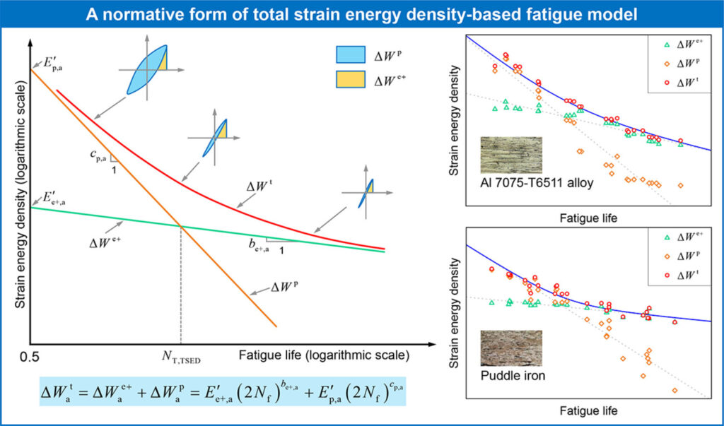
Total Strain Energy Density (TSED) Approach
Halford (1966) established that the plastic strain energy density per cycle — the area of the hysteresis loop — correlates with fatigue life across a wide range of metals. For a stabilized hysteresis loop with plastic strain range $\Delta\varepsilon_p$ and stress range $\Delta\sigma$: $$\Delta W_p \approx \frac{\Delta\sigma \cdot \Delta\varepsilon_p}{2} \quad \text{(for Masing materials)}$$ The fatigue life relationship takes the form: $$\Delta W_p \cdot N_f^\beta = C_p$$ where $\beta$ and $C_p$ are material constants. This energy-life relationship parallels the Coffin-Manson strain-life equation but uses a scalar energy parameter rather than plastic strain amplitude.
Ellyin-Kujawski Total Strain Energy Density
Ellyin and Kujawski (1984) extended the plastic SED approach by adding the positive elastic strain energy density to the total damage parameter. Their key physical insight was that compressive stresses contribute negligibly to fatigue damage — crack faces close under compression and the driving force for crack advance disappears. Only the positive (tensile) portion of the elastic SED should be counted: $$\Delta W^+= \frac{(\Delta\sigma)^2}{2E} \quad \text{(when } \sigma_{\max} > 0\text{)}$$ $$\Delta W^+ = \frac{\sigma_{\max}^2}{2E} \quad \text{(for partial compression cycles)}$$ The total SED fatigue parameter is then: $$\Delta W_{\text{total}} = \Delta W_p + \Delta W^+$$ This formulation naturally accounts for mean stress effects: a positive mean stress increases $\Delta W^+$ without changing $\Delta W_p$, raising the total damage parameter and reducing life — consistent with the Goodman-type mean stress correction but derived from energy principles rather than empirical fitting.
The energy-life relationship in the Ellyin-Kujawski framework takes the form: $$\Delta W_{\text{total}} = A \cdot N_f^\gamma + B$$ where $A$, $\gamma$, and $B$ are material constants determined from strain-controlled fatigue tests at multiple strain amplitudes and load ratios.
Advantages of the TSED Approach
* Unified HCF/LCF description: In the high-cycle fatigue (HCF) regime, plastic strain energy is negligible and the elastic term dominates; in the low-cycle fatigue (LCF) regime, plastic dissipation dominates. A single TSED formulation spans both regimes without the need to switch between S-N and Coffin-Manson frameworks.
* Intrinsic mean stress correction: The positive elastic energy formulation provides a physically motivated mean stress effect without requiring a separate Goodman or Morrow correction.
* Multiaxial applicability: Because energy is a scalar, the TSED approach extends to multiaxial stress states — including combined axial-torsion, biaxial tension, and non-proportional loading — without the plane-selection ambiguity that plagues critical plane approaches
* Independence from stress/strain decomposition: For materials with significant kinematic hardening, decomposing total strain into elastic and plastic components can be ambiguous. The total energy approach sidesteps this issue.
The Averaged SED Approach for Notched Components: Lazzarin and Berto
The most significant recent development in SED-based fatigue assessment is the averaged strain energy density (ASED) approach developed by Paolo Lazzarin.and Filippo Berto at the University of Padova, beginning with Lazzarin and Zambardi (2001) and developed extensively through the 2000s and 2010s.
The Core Concept
The key innovation of the ASED approach is to evaluate not the SED at a point but the SED averaged over a finite control volume surrounding the notch tip or weld toe. The control volume is a circle (in 2D) or a torus (in 3D) of radius $R_0$ centered at the notch tip.
The averaged SED is defined as: $$\bar{W} = \frac{1}{V} \int_V W \, dV$$ where $V$ is the volume of the control region.
The fracture or fatigue criterion is then: $$\bar{W} = \bar{W}_{cr} \quad \text{(fracture)} \quad \text{or} \quad \Delta\bar{W} = \Delta\bar{W}_{cr} \quad \text{(fatigue)}$$ where $\bar{W}_{cr}$ and $\Delta\bar{W}_{cr}$ are material-dependent critical values. The Control Radius $R_0$ The control radius $R_0$ is a material property, not a geometric parameter. It is determined from known material fatigue and fracture properties.
For fatigue under Mode I loading: $$R_0 = \frac{1}{2\pi}\left(\frac{\Delta K_{\text{th}}}{\Delta\sigma_w}\right)^2$$ where $\Delta K_{\text{th}}$ is the long-crack threshold stress intensity factor range and $\Delta\sigma_w$ is the plain specimen fatigue limit (stress range at $10^7$ cycles, $R = -1$). This definition connects $R_0$ to the El Haddad short crack parameter and to the material’s notch sensitivity.
For brittle fracture: $$R_0 = \frac{(1-2\nu)^2}{4\pi} \cdot \left( \frac{K_{Ic}}{\sigma_u} \right)^2$$ where $\sigma_u$ is the ultimate tensile strength.
Typical values of $R_0$ range from fractions of a millimeter for high-strength steels (where the fatigue-sensitive process zone is small) to several millimeters for cast iron or weld metal (where microstructural heterogeneity makes the process zone larger).
Key Properties of the ASED Approach
* Mesh insensitivity: This is a major practical advantage. The point-wise stress singularity at a sharp notch tip requires extremely fine finite element meshes for convergence. The averaged SED over a control volume converges rapidly with mesh refinement and can be computed accurately from coarse meshes — Lazzarin, Berto, and Zappalorto (2010) demonstrated that accurate calculations are possible from FE models with element sizes of the same order as $R_0$. This dramatically reduces computational cost.
* Notch geometry independence: A remarkable feature of the ASED approach is that different notch geometries (V-notches, U-notches, blunt notches, cracks) with different opening angles and radii but the same $R_0$ and the same $\bar{W}_{cr}$ lie on a single master fatigue scatter band.
* Unified static and fatigue assessment: The same control volume and critical energy can be used for both static fracture prediction and fatigue life prediction, providing a consistent framework for multi-regime assessment.
Application to Welded Joints
The ASED approach has found particularly successful application to welded joint fatigue, where it addresses a long-standing difficulty: weld toe and weld root geometries vary from joint to joint, making nominal stress or hot-spot stress approaches unreliable without tight geometric tolerances.
In the ASED framework, both weld toe and weld root are modeled as sharp V-notches with opening angles of $135^\circ$ and $0^\circ$ respectively (standard idealization for fillet welds). The control radius $R_0 \approx 0.28\text{ mm}$ for structural steel has been validated against thousands of fatigue data points from welded joints of varied geometry.
Lazzarin, Berto, and colleagues showed that fatigue data from steel welded joints of very different geometry — cruciform joints, T-joints, butt welds, lap joints — all fall within a narrow scatter band when plotted as $\Delta\bar{W}$ vs. $N_f$. Application to Additive Manufacturing (AM)
In recent years, the ASED method has emerged as a frontline tool for assessing components produced via Additive Manufacturing (AM), such as Laser Powder Bed Fusion (LPBF) or Electron Beam Melting (EBM).
As-built AM components are inherently plagued by complex, random material defects:
* High surface roughness and stair-case effects acting as micro-notches. * Internal porosity (gas pores and keyhole defects). * Lack-of-fusion zones characterized by sharp, un-melted boundary shapes.
Classical fatigue frameworks struggle here because modeling the exact morphology of thousands of microstructural defects is computationally impossible. The ASED framework bypasses this entirely. By averaging the energy over a control volume $R_0$, the method effectively smooths out local geometric micro-irregularities while capturing their global energy impact.
By adjusting the material characteristic radius $R_0$ to account for both the matrix alloy properties and the manufacturing process print quality, engineers can reliably predict the fatigue life of unmachined, highly irregular AM structural parts using relatively coarse, macro-level finite element meshes.
Connecting SED to LEFM: The Paris Law in Energy Terms
The Paris law for fatigue crack growth: $$\frac{da}{dN} = C (\Delta K)^m$$ can be recast in SED terms. Since $\Delta K^2 \propto \Delta W$ (energy release rate $G = \frac{K^2}{E}$ for plane stress), the Paris law is fundamentally an energy-based relationship. Specifically, for a crack advancing by $\Delta a$ per cycle: $$\Delta W \propto \frac{\Delta K^2}{E} \propto \left( \frac{da}{dN} \right)^{\frac{2}{m}}$$ This connection shows that the TSED fatigue parameter and the Paris law FCGR are manifestations of the same underlying physics — energy driving crack advance — expressed at different length scales. The SED approach is most naturally applicable to crack initiation and the early propagation phase; Paris law LEFM applies once a dominant crack is well-established and propagating in a $K$-controlled manner.
Practical Implementation
Step 1: Material Characterization Determine basic properties ($\Delta\sigma_w$, $\Delta K_{\text{th}}$, $K_{Ic}$, $E$, $\nu$) from standard specimen tests. Compute the control radius: $$R_0 = \frac{1}{2\pi}\left(\frac{\Delta K_{\text{th}}}{\Delta\sigma_w}\right)^2$$ Step 2: FE Model Construction Build a finite element model of the component. Mesh refinement within the control volume is not strictly required; an element size of the order of $R_0$ is sufficient. Apply a nominal unit load.
Step 3: Extract Averaged SED Sum the element strain energies within the control radius $R_0$ and divide by the total volume of that control zone to find $\bar{W}_{\text{unit}}$. For a linear elastic analysis under a cyclic stress range $\Delta\sigma$: $$\Delta\bar{W} = \bar{W}_{\text{unit}} \cdot (\Delta\sigma)^2$$ Step 4: Fatigue Life Estimation Compare $\Delta\bar{W}$ to the material’s master $\Delta\bar{W}$ vs. $N_f$ curve to find the predicted life. For variable amplitude loading, use the Palmgren-Miner rule in energy terms: $$D = \sum \frac{n_i}{N_{f,i}}$$ Worked Example: Fillet-Welded Cruciform Joint
Consider a steel cruciform joint ($S355$ steel, $f_y = 355\text{ MPa}$) loaded in axial tension with a nominal stress range $\Delta\sigma_{\text{nom}} = 100\text{ MPa}$. The weld toe is modeled as a sharp V-notch with an opening angle of $135^\circ$. Material properties for S355: * $\Delta\sigma_w = 155\text{ MPa}$ (plain specimen, $R = 0$, $2\times10^6$ cycles) * $\Delta K_{\text{th}} = 180\text{ N/mm}^{3/2}$ at $R = 0$ * $E = 206,000\text{ MPa}$, $\nu = 0.3$ Control radius calculation: $$R_0 = \frac{1}{2\pi}\left(\frac{180}{155}\right)^2 = 0.212\text{ mm} \approx 0.28\text{ mm} \quad \text{(standard literature value for this steel class)}$$ FE analysis & Life prediction: Extracting $\bar{W}_{\text{unit}}$ over the $R_0 = 0.28\text{ mm}$ control circle yields $\Delta\bar{W} = \bar{W}_{\text{unit}} \times (100)^2$. Locating this energy on the master SED curve for structural steel components yields a predicted fatigue life of $N_f \approx 2\times10^6$ cycles. This correlates cleanly with the traditional International Institute of Welding (IIW) fatigue class FAT 71 guidelines, while validating the design completely via energy fields.
Comparison with Other Approaches
| Method | Basis | Multiaxial | Notch Geometry | Mesh Sensitivity | Mean Stress |
|---|---|---|---|---|---|
| Nominal S-N | Stress amplitude | Limited | Embedded in FAT class | N/A | Goodman correction |
| Hot-spot stress | Extrapolated surface stress | Limited | Partially removed | Moderate | Goodman correction |
| Effective notch stress | Fictitious radius ($r=1\text{mm}$) | Limited | Removed | High | Goodman correction |
| Critical plane | Stress/strain on plane | Good | Requires notch analysis | High | Intrinsic |
| TSED (Ellyin) | Total energy/cycle | Excellent | Requires notch analysis | High at point | Intrinsic |
| ASED (Lazzarin-Berto) | Averaged energy density | Good | Removed via $R_0$ | Low (coarse mesh) | Intrinsic |
| LEFM Paris law | $\Delta K$ | Mode-specific | Crack only | Moderate | R-ratio |
* Large-scale Plasticity: The ASED approach as formulated by Lazzarin and Berto is primarily linear elastic. Under large-scale yielding ($\Delta\sigma_{\text{nom}} > 0.7 \sigma_y$), corrections via Neuber’s rule or the Equivalent Strain Energy Density (ESED) method are required.
* Non-proportional Multiaxial Loading:* When principal stress directions rotate significantly during a cycle, simple scalar energy summation can lose accuracy unless supplementary phase-angle terms are added.
* Pure Propagation Problems: For damage-tolerant structures where tracking macro-crack propagation step-by-step is required, the LEFM Paris Law e the preferred alternative.
Summary
The strain energy density method provides a powerful, physics-based framework where energy stored or dissipated per unit volume governs structural degradation. By deploying Sih’s $S$ factor for mixed-mode environments, Ellyin’s TSED for HCF/LCF bounds, or Lazzarin and Berto’s ASED for mesh-insensitive notched and additive design, engineering groups gain a flexible tool capable of unifying fatigue profiles where classical stress/strain parameters fall short.
References
Sih, G.C. (1974). Strain-energy-density factor applied to mixed mode crack problems. *International Journal of Fracture*, 10, 305–321.
Halford, G.R. (1966). The energy required for fatigue. *Journal of Materials*, 1, 3–18.
Ellyin, F., Kujawski, D. (1984). Plastic strain energy in fatigue failure. *Journal of Pressure Vessel Technology*, 106(4), 342–347.
Lazzarin, P., Zambardi, R. (2001). A finite-volume-energy based approach to predict the static and fatigue behavior of components with sharp V-shaped notches. *International Journal of Fracture*, 112(3), 275–298.
Lazzarin, P., Berto, F., Gomez, F.J., Zappalorto, M. (2008). Some advantages derived from the use of the strain energy density over a control volume in fatigue strength assessments of welded joints. *International Journal of Fatigue*, 30(8), 1345–1357.
Lazzarin, P., Berto, F., Zappalorto, M. (2010). Rapid calculations of notch stress intensity factors based on averaged strain energy density from coarse meshes. *International Journal of Fatigue*, 32(10), 1559–1567.
Berto, F., Mutignani, F., & Marangon, C. (2016). Fatigue assessment of additive manufactured parts by means of the local strain energy density. *Theoretical and Applied Fracture Mechanics*, 84, 114-125.
Tom Irvine | VibrationData.com | Structural Dynamics, Shock, Vibration & Acoustics
📌 Related Guide & Knowledge Hub
This article is part of our comprehensive collection on Multiaxial Stress & Vibration Fatigue Analysis . Explore the full hub for methods on strain energy density, random vibration, and low-cycle fatigue.
Thanks, perhaps a better prediction for crack initiation.