Question:
What is meant exactly by “fatigue exponent”. I generally input a value between 3 (for notched parts) and 6 (for (unnotched ones). Is it right?…I’ve found confusing and contrasting definitions about b and m exponent (among MIL-STD-810 G and various other documents)
Answer:
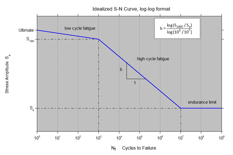
The fatigue exponent is calculated from the slope of the high cycle SN curve in log-log format as indicated by variable b in the above plot. The fatigue exponent is actually 1/b. It is the greatest uncertainty factor in fatigue analysis.
The slope can be affected by many factors including stress concentration, notches, mean stress, residual stress, surface roughness, temperature, corrosion, etc.
Steel with a welded joint has a slope of 3 to 3.5.
Steinberg’s text recommends 6.4 for electronic components.
For bare aluminum, I would use 9 or 10.
A good approach would be to run three cases using lower, nominal, and upper estimates for the fatigue exponent.
Damping is another uncertainty factor. So you should probably also vary the Q value.
So now you will have permutations for both the fatigue exponent and Q.
Here are some references: