A large welded machine base comes out of the fabrication shop looking straight and square. It goes to the machine shop, where the mounting pads are milled flat to a few hundredths of a millimetre. The next morning the pads are out of flat again. Nothing was dropped and nothing was overloaded. The weld residual stresses that were locked in the part found a new equilibrium once the machining removed some of the material that had been carrying them, and the part moved to get there.
The traditional cure is a furnace. Thermal stress relief heats the whole part until the yield strength falls below the residual stress, lets the material creep and yield until the stress has nowhere left to go, and then cools it slowly. It works, but it needs a furnace big enough for the part, many hours of fuel, and a material that can tolerate the heat. Vibratory stress relief (VSR) is the alternative: clamp a vibrator to the part, shake it at or near its resonant frequencies for tens of minutes, and let the cyclic stress do the job that the heat would have done.
VSR has been in shop use since the 1940s and it still divides opinion. Some engineers use it routinely on weldments that must stay flat after machining. Others regard it as a process that has never quite explained itself. Both groups have a point, and the structural dynamics of the part goes a long way toward explaining why.
A Short History
Hammering a casting or a weld to relieve it is far older than any vibrator, and foundries long relied on natural aging, leaving castings outdoors for months before machining. The engineered process dates from the Second World War. McGoldrick and Saunders documented U.S. Navy use of vibration to stabilize large shipyard jigs, fixtures and castings in a 1943 paper in the Journal of the American Society of Naval Engineers. German engineers, short of furnace capacity for large fabrications, noticed that welded parts which had been trucked between shops before machining were more stable than those machined in place, and the jolting of the journey was credited with the improvement.
Commercial equipment followed in the postwar decades, particularly for paper mill machinery, where long stainless and bimetallic parts did not respond well to furnace treatment. In the 1980s and 1990s Bonal Technologies developed its Meta-Lax process, which dwells below resonance rather than at it, and a 1999 U.S. Department of Energy fact sheet reported about 1,200 units in American service. That fact sheet also repeats the vendor claim that the process can substitute for 80 to 90 percent of heat-treatment stress relief. Claims of that kind come from the supplier, not from independent residual stress measurements, and they should be read that way.
How the Treatment Is Done
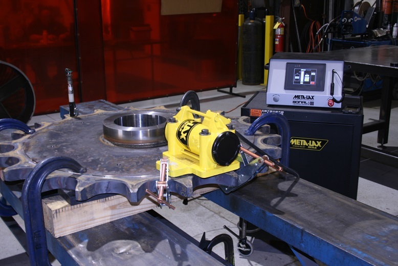
The part is set on rubber isolators so that it is effectively free-free, with the supports placed near the nodal lines of the modes that will be excited. An electric motor with an adjustable eccentric mass is clamped to the part, usually near an antinode, and an accelerometer is mounted at a second location. The controller sweeps the motor speed slowly upward and records the response, which identifies the resonant frequencies of the part on its isolators.
View larger image
Figure 1. A Meta-Lax vibratory stress relief setup. The yellow eccentric-mass vibrator is clamped to a large sprocket weldment, with the controller behind it. Photo: Brewer Machine.
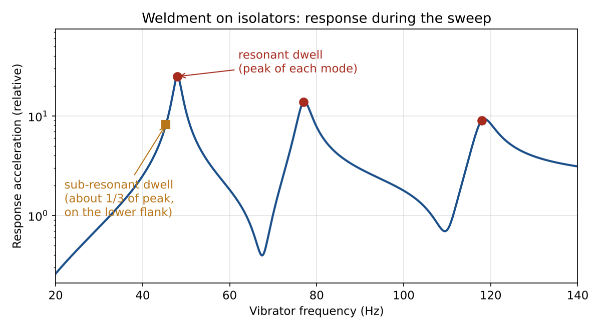
The treatment itself is a dwell. In the resonant method the vibrator is held at or near each resonance peak in turn. In the sub-resonant method, the approach behind Meta-Lax, the vibrator is held on the lower flank of a peak where the response is a fraction of the peak value. Figure 2 shows the two dwell points on a synthetic three-mode weldment. The Welding Institute (TWI) based in Cambridge, UK notes that both methods can be effective, with the resonant method the more effective of the two.
View larger image
Figure 2. Synthetic sweep response of a weldment on isolators, with modes at 48, 77 and 118 Hz and 2 percent damping. The response rises with frequency squared because the eccentric mass force does. Resonant dwells sit on the peaks; the sub-resonant dwell sits at about one third of the first peak.
Operators watch the resonance during the dwell. The usual signature reported for a successful treatment is that the peak shifts slightly in frequency and changes in height during the first minutes, then stops changing. The stabilized curve is taken as evidence that the part has finished relaxing. That signature is consistent with a small loss of stiffness or a change in damping as local yielding occurs, but it is an indirect indicator. It says that something in the part changed, not how much residual stress was removed.
The Mechanism, and the Puzzle
The simplest explanation is superposition. A weld leaves a tensile residual stress $\sigma_r$ near the weld, often close to the yield stress $\sigma_y$ of the parent metal. Vibration adds a cyclic stress of amplitude $\sigma_a$. Where the sum exceeds yield,
$$\sigma_r+\sigma_a>\sigma_y$$
the material yields locally on the peak of the cycle. For an elastic-perfectly-plastic material, the residual stress left after the vibration stops is
$$\sigma_{r,\,after}=\min\left(\sigma_r,\;\sigma_y-\sigma_a\right)$$
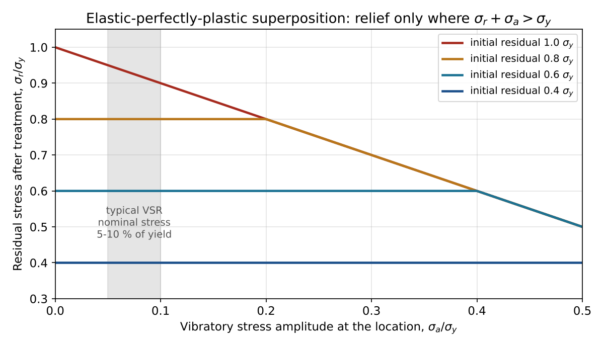
Figure 3 plots this relation for four levels of initial residual stress. The model is crude, but it captures the essential behavior: vibration relieves only the stress that is already near yield, and it relieves it by roughly the vibratory amplitude. A location at 40 percent of yield is untouched by anything less than a 60 percent of yield vibration.
View larger image
Figure 3. Residual stress after vibration for an elastic-perfectly-plastic material. Relief begins only where the residual plus the vibratory amplitude reaches yield, and below that point the vibration does nothing.
Here is the puzzle. Walker’s 2011 review in the Proceedings of the IMechE, Part L notes that VSR equipment typically applies only about 5 to 10 percent of the yield stress. Read off Figure 3, that would trim a yield-level weld residual stress by 5 to 10 percent and leave everything else alone. Yet users report useful stabilization, and TWI states that VSR is capable of giving dimensional stability equal to that of thermal stress relief. Several effects close part of the gap.
- Stress concentration. The 5 to 10 percent figure is a nominal stress. At a weld toe, a fillet, or a section change, the local vibratory stress can be two or three times higher, and that is also where the residual stress peaks.
- Cyclic softening and the Bauschinger effect. Weld metal and heat-affected zones that have already been plastically strained by the welding thermal cycle can yield in reverse at a stress well below the monotonic yield stress. Repeated cycling also lowers the effective yield of some steels.
- Microplasticity. Dislocations can move locally at stresses below the macroscopic yield point, so some relaxation occurs even where the simple model predicts none.
- Retained austenite. Walker proposed that in steel weldments the vibration helps transform small particles of retained austenite to martensite, and that the shear strain of the transformation relaxes the surrounding residual stress. He offered this as a hypothesis, and it would apply only to materials that contain retained austenite.
The more practical point is that dimensional stability and stress reduction are not the same requirement. A part distorts during machining because the material being cut away was carrying part of the residual stress field. The peaks of that field, the regions sitting at or near yield, are the ones most able to redistribute. Knocking the peaks down by even 10 or 20 percent can remove much of the stored strain energy that would otherwise be released by the cutter, while leaving the average residual stress largely as it was.
Key point. VSR is best understood as a peak-shaving process. It works on stress that is already close to yield, at locations where the vibration produces significant cyclic stress. It does not lower a residual stress field uniformly the way a furnace does.
Mode Shapes Decide Where the Relief Goes
The vibratory stress in a resonating part is not uniform. It follows the curvature of the mode shape. For a beam-like weldment vibrating in bending in mode $n$ with modal coordinate $q_n$, the surface bending stress is
$$\sigma_a(x)=E\,c\,\phi_n”(x)\,q_n$$
where $E$ is the elastic modulus, $c$ is the distance from the neutral axis to the surface, and $\phi_n”$ is the curvature of the mode shape. The stress is zero wherever the curvature is zero. On a free-free beam that means the ends, where the bending moment must vanish, and for the higher modes it also means interior points where the curvature changes sign.
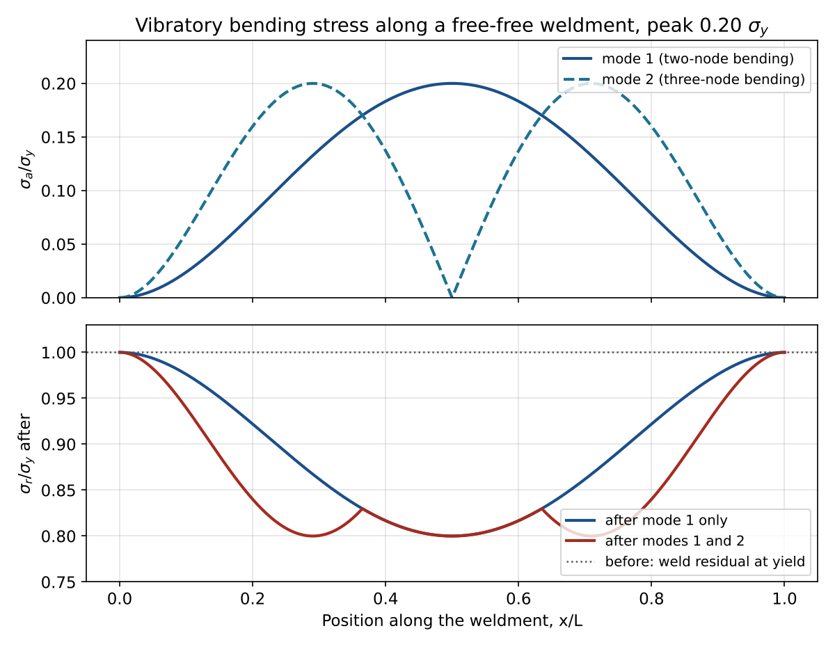
Figure 4 shows the consequence for a free-free weldment with a weld residual stress at yield along its full length. The first mode is driven until its peak stress reaches 20 percent of yield. That peak occurs at mid-length, and the relief falls away toward the ends: at one tenth of the length from an end, the first mode applies only 2.4 percent of yield. Adding the second mode, whose peaks sit near 0.29 and 0.71 of the length, fills in much of the gap. The ends, however, receive no relief from any bending mode.
View larger image
Figure 4. Top: vibratory bending stress along a free-free uniform beam in its first two bending modes, each scaled to a peak of 0.20 yield. Bottom: residual stress remaining after treatment, from the elastic-perfectly-plastic model, starting from a yield-level weld residual stress everywhere.
This is why experienced operators treat several resonances rather than one, and why the location of the vibrator and the supports matters. A weld that sits on a nodal line of every mode that was excited has not been treated, whatever the controller display says. Torsional and plate-like modes put their stress in different places from the bending modes, and a complex weldment may need modes of more than one type to reach its critical welds. A modal survey or a quick finite element model, run before treatment, identifies which modes stress which welds.
The Fatigue Cost
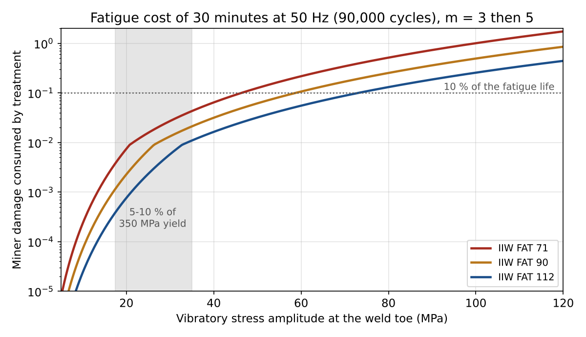
VSR is, by construction, a fatigue test. A 30 minute dwell at 50 Hz applies 90,000 cycles. Whether that matters depends on the stress range at the most fatigue-critical weld detail. Using the International Institute of Welding (IIW) nominal stress curves, with slope $m=3$ through $2\times10^6$ cycles at the FAT class stress range and slope 5 below the knee at $10^7$ cycles, the cycles to failure at stress range $\Delta\sigma=2\sigma_a$ are
$$N=2\times10^6\left(\frac{\text{FAT}}{\Delta\sigma}\right)^3$$
and the Miner damage consumed by $n$ treatment cycles is $D=n/N$. Using the slope 5 extension below the knee is conservative for a constant amplitude dwell, since IIW treats the knee as a constant amplitude fatigue limit, but residual stress relaxation during the treatment makes a cutoff hard to defend. Figure 5 and Table 1 show the result.
View larger image
Figure 5. Miner damage consumed by 90,000 cycles at the weld toe for three IIW detail categories, using slope 3 above the knee and slope 5 below it. The shaded band is 5 to 10 percent of a 350 MPa yield stress.
| Weld toe stress amplitude | FAT 71 | FAT 90 | FAT 112 |
|---|---|---|---|
| 35 MPa (10 percent of 350 MPa yield) | 4.3 % | 2.1 % | 1.1 % |
| 70 MPa (20 percent of 350 MPa yield) | 35 % | 17 % | 8.8 % |
Table 1. Fraction of fatigue life consumed by a 30 minute, 50 Hz dwell.
At the nominal levels that VSR equipment normally applies, the cost is a few percent of the life of a typical welded detail. Doubling the amplitude to get more relief raises the cost about eightfold, and a poor detail can lose a third of its life in half an hour. The tension between the two is plain: the stress amplitude that relieves the most residual stress is also the one that consumes the most fatigue life, and it does so at the same weld toes.
The experimental record is more encouraging than that arithmetic suggests. Munsi, Waddell and Walker, writing in Strain in 2001, compared welded fatigue specimens in three conditions. Relative to the as-welded specimens, vibratory treatment raised fatigue life by 17 to 30 percent, while thermal stress relief lowered it by 43 percent. The likely explanation for the vibratory gain is that removing tensile residual stress at the weld toe lowers the effective mean stress of every later service cycle, which can outweigh the damage spent during treatment. The authors themselves noted that the mechanism remains poorly understood. TWI’s advice is the sensible middle ground: VSR should be used judiciously in fatigue-sensitive applications.
Practical rule. Know the vibratory stress at the critical welds before the dwell, not after. A strain gage on the worst weld toe during the sweep converts the treatment from a black box into a known stress history that can be checked against the fatigue curve for that detail.
What Vibration Cannot Do
Thermal stress relief does more than lower residual stress, and none of its other effects come from vibration. Table 2 sets the two processes side by side.
| Attribute | Thermal stress relief | Vibratory stress relief |
|---|---|---|
| Peak residual stress reduction | Typically 70 to 80 percent (TWI); rarely complete | Variable and hard to predict; concentrated at stress peaks that the modes reach |
| Dimensional stability for machining | Good | Can equal thermal relief (TWI), depending on equipment and operator skill |
| Tempering of hard heat-affected zones | Yes | No |
| Hydrogen removal | Yes, at temperature | No |
| Effect on fatigue life | Can lower it; 43 percent loss in one study | Consumes some life during treatment; 17 to 30 percent gain in the same study |
| Part size and material limits | Furnace size; heat-sensitive, bimetallic and precision-finished parts are a problem | Practically none on size; part must be excitable at useful amplitude |
| Time | Hours, including heating and controlled cooling | Tens of minutes |
| Code acceptance in lieu of PWHT | Specified by the codes | Not accepted by the American welding and pressure vessel codes |
Table 2. Thermal and vibratory stress relief compared.
The code row deserves emphasis. Where postweld heat treatment is required by a structural welding code or a pressure vessel code, it is required for metallurgical reasons as well as for residual stress: tempering hard martensitic zones, driving out hydrogen, and restoring toughness. Vibration does none of these, and it is not accepted in place of PWHT. VSR belongs on non-code work, and its natural home is the large machine base, frame, bed or fixture that must hold its shape through machining and service.
The same reasoning applies to stress corrosion cracking. Where the concern is a tensile residual stress field below the threshold for stress corrosion, partial relief at the peaks is not a guarantee that the remaining field is below that threshold everywhere. That is a case for thermal relief, or for measurement.
Doing It Well
The structural dynamics of the part suggests a short procedure.
- Find the modes first. A sweep on the isolators, or a simple finite element model, identifies the modes and where each one puts its stress. Pick modes whose high-stress regions cover the welds that matter.
- Support at nodes, drive at antinodes. Isolators placed at antinodes add damping and absorb the energy the vibrator is trying to put into the part. A vibrator placed at a node cannot excite that mode at all.
- Treat several modes. One mode leaves gaps, as Figure 4 shows, including at free ends where no bending mode applies any stress.
- Measure the stress you are applying. An accelerometer reading at one point does not tell you the stress at a weld toe elsewhere. A strain gage at the critical weld does, and it bounds the fatigue cost.
- Do not stop at the resonance signature. A peak that has stopped shifting tells you the dwell has done what it is going to do at that amplitude and location. It does not tell you how much residual stress is left.
- Qualify the process on the product. For a production part, measure residual stress before and after treatment on a representative piece, by hole drilling per ASTM E837 or by X-ray diffraction, and check dimensional stability through rough and finish machining. TWI notes that success depends on both the equipment and the operator, and qualification is how you find out whether yours succeeded.
Where Research Is Heading
Current work is aimed at the gaps that have kept VSR on the margin of the codes: finite element models that combine the residual stress field from a welding simulation with cyclic plasticity under the modal stress, and hybrid treatments. Thermal-vibratory stress relief, which vibrates a part at a moderately elevated temperature where the yield stress is lower, has been studied on titanium alloys such as Ti6Al4V and on aluminum alloys. Both directions point the same way. The process works best when the vibratory stress, the residual stress and the local yield strength are known together at the locations that matter, which is exactly the information the original shop process did without.
Summary
Vibratory stress relief is real, useful and limited. It works by adding cyclic stress to a residual stress field until the peaks yield, which makes it a peak-shaving process rather than a uniform one. Its effect follows the mode shapes, so where the vibrator goes and which modes are excited determine which welds are treated. It spends some fatigue life to do its work, and the amplitude that buys the most relief is also the most expensive. It does nothing metallurgical, and it is not a code substitute for postweld heat treatment. For large non-code weldments that must stay flat after machining, it is often the most practical tool available, provided it is treated as a structural dynamics problem rather than as a box with a dial.
For more on resonance, fatigue and the stress-velocity relationship, see the free Vibrationdata ebooks at blog.vibrationdata.com/2025/11/27/toms-ebooks/.
References
- C. Walker, “A theoretical review of the operation of vibratory stress relief with particular reference to the stabilization of large-scale fabrications,” Proceedings of the Institution of Mechanical Engineers, Part L: Journal of Materials: Design and Applications, 225(3), 195-204, 2011.
- A.S.M.Y. Munsi, A.J. Waddell and C.A. Walker, “The influence of vibratory treatment on the fatigue life of welds: a comparison with thermal stress relief,” Strain, 37(4), 142-150, 2001.
- TWI, “Is vibratory stress relief as effective as thermal stress relief?” Technical knowledge FAQ.
- McGoldrick and Saunders, “Experiments in Stress-Relieving Castings and Welded Structures by Vibration,” Journal of the American Society of Naval Engineers, 55(4), 589-609, 1943.
- U.S. Department of Energy, Office of Industrial Technologies, “Meta-Lax Stress Relief Process Saves Energy,” DOE/GO-10099-851, 1999.
- VSR Technology Group, “Vibratory Stress Relief Historical Overview.”
- A. Hobbacher, Recommendations for Fatigue Design of Welded Joints and Components, 2nd edition, Springer, 2016 (IIW document IIW-2259-15).
- ASTM E837, Standard Test Method for Determining Residual Stresses by the Hole-Drilling Strain-Gage Method.