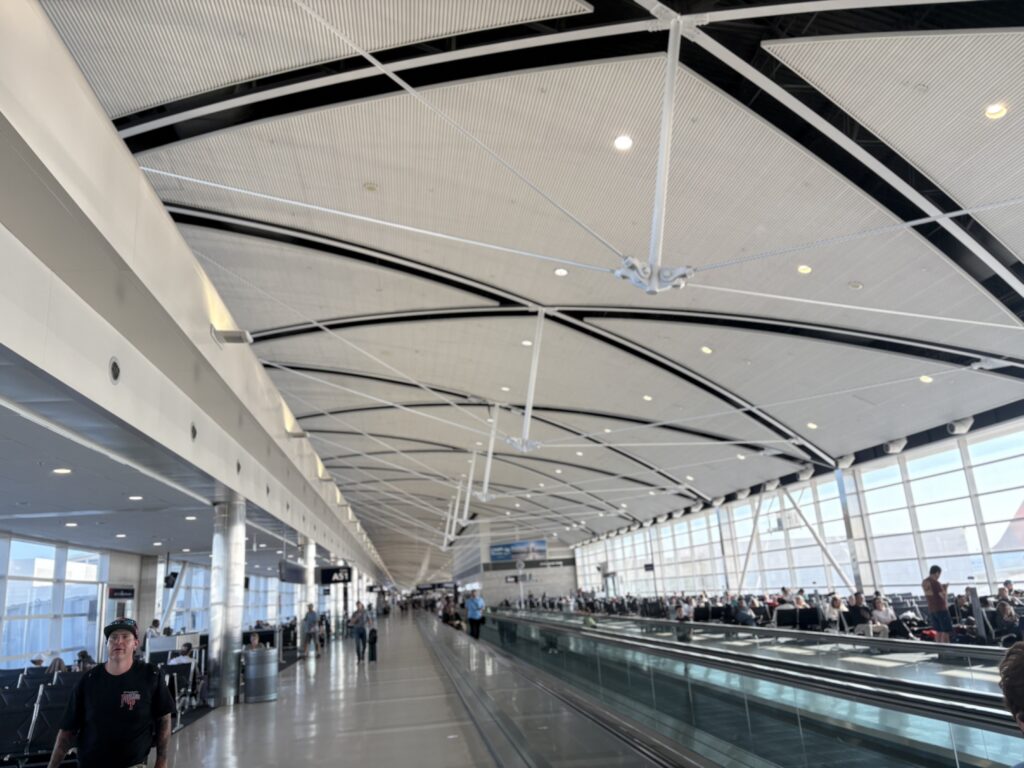
Structural Dynamics Series — Detroit Metropolitan Wayne County Airport (DTW), McNamara Terminal, Concourse A
Introduction
The McNamara Terminal at Detroit Metropolitan Wayne County Airport opened on February 24, 2002. It was designed by SmithGroup and built by Hunt Construction. Concourse A is nearly one mile long, making it the longest linear airport concourse in the United States. Overhead, the exposed structural system is a signature architectural element: a series of arched roof panels supported by a repeating scheme of steel struts and tension rods, providing column-free spans of up to 87 feet.
Walking through the concourse, three distinct structural elements are visible from below:
- Arched roof panels spanning transversely across the concourse, forming a shallow barrel vault.
- Steel struts that extend downward from the underside of the arch, meeting at a common node below the roof plane.
- Lateral tie rods (small-diameter tension cables) running horizontally between the strut tips at each bay.
The geometry is not decorative. Each element performs a specific mechanical function tied to the load path from snow, dead load, wind, and live load down to the supporting columns. This post walks through the mechanics.
The Structural System — An Inverted King Post Arrangement
The arrangement is best described as an inverted king post truss, sometimes called a tension truss or underslung truss. The traditional king post truss has a compression post above the tie beam. Here, the roles are reversed: the arched panel is the compression chord above, and the vertical steel member hangs below it as a strut in compression, pushing down against a set of thin tension rods that are anchored back up to the arch at the shoulders.
Function of each element
| Element | Load Type | Function |
|---|---|---|
| Arched roof panel | Compression (with bending) | Spans transversely; carries snow, dead, wind, and live loads; develops horizontal thrust at supports. |
| Downward steel strut | Compression | Pushes downward against the tie rods at midspan, creating an upward reaction on the arch (pre-camber effect). |
| Lateral tie rod | Pure tension | Resists horizontal thrust of the arch; ties the two spring points together so the arch cannot spread. |
| Perimeter columns | Compression | Deliver total vertical reaction to the foundation. |
Why the strut points down, not up
In a conventional trussed rafter, a king post above the tie beam hangs the middle of the beam up. Here, the arch already wants to sag under gravity load. The downward strut, working with the tension rods anchored at the arch shoulders, applies an upward point load at the arch midspan through cable action. It is a form of post-tensioning by geometry: tightening the tie rod pulls the strut down, which pulls the arch shoulders inward, which pushes the arch crown up. The result is a shallower, thinner arch than would be possible with the arch acting alone.
Why the tie rod is horizontal
An arch resting on two supports pushes outward at those supports. That outward push is called thrust. Any masonry arch, roman aqueduct, or cathedral vault must resolve this thrust either through massive buttresses or through a tension tie across the springline. The horizontal cable in the DTW roof is that tension tie, sized to carry the full horizontal component of the arch reaction so the columns below see only vertical load.
Arch Thrust — The Governing Equation
For a shallow arch carrying a uniformly distributed load $w$ (force per unit length) over span $L$ with rise $h$, the horizontal thrust at each springline is:
$$H \;=\; \frac{w L^{2}}{8 h}$$This is the same equation used for parabolic cables and is a very useful first-order estimate. The equation says two important things:
- Doubling the load doubles the tie rod tension.
- Halving the rise doubles the tie rod tension.
Shallow arches look elegant but demand large tension ties. That is why the DTW rods, though visually thin, are high-strength steel and sized for a load that is a large multiple of their self-weight.
Worked example. Assume a bay tributary width of 20 ft, span $L = 80$ ft, rise $h = 6$ ft, and a total design load (dead + snow) of $w = 40$ psf. The line load on the arch is $40 \times 20 = 800$ plf. The horizontal thrust is:
$H = (800)(80)^{2} / (8 \times 6) = 106{,}700$ lb, or about 53 tons per tie rod.
A 1⅓-inch diameter high-strength steel rod (Fu = 150 ksi) has an ultimate capacity of roughly 190 kips, providing a comfortable margin for load factors and drift surcharge.
Roof Loads for Southeast Michigan
The design loads for this roof are governed by the Michigan Building Code and ASCE 7. For Wayne County, the following values are typical of the McNamara Terminal design vintage.
| Load Category | Value | Basis |
|---|---|---|
| Dead load (roof panels, framing, MEP) | 15 to 25 psf | Actual construction takeoff |
| Ground snow load, pg | 25 psf | ASCE 7-22 for Wayne County, MI |
| Flat roof snow load, pf | ~20 psf | pf = 0.7 Ce Ct Is pg, heated, exposed, Risk Cat III |
| Curved roof snow load | Varies along arch | ASCE 7 Chapter 7 unbalanced load case |
| Roof live load | 20 psf, reducible | MBC 1607, ASCE 7-22 |
| Basic wind speed | ~105 mph | ASCE 7-22 Risk Category III, Detroit |
| Seismic Design Category | SDC B (typical) | Low seismicity, Site Class D assumed |
Unbalanced snow load on a curved roof
For an arched roof, ASCE 7 Section 7.6.2 requires an unbalanced snow case in which the leeward side receives a triangular surcharge and the windward side is unloaded. This case is often more critical than uniform snow because it applies an asymmetric line load that induces bending in the arch and can significantly increase the tie rod tension on one side. Curved and arched roofs must be checked for both:
- Balanced case: uniform pf across the full arch.
- Unbalanced case: zero on windward, up to 2 pf on leeward.
Wind loads and uplift
The curved barrel-vault geometry generates significant uplift on the windward slope and along the crown due to accelerated flow. For lightweight roofs, ASCE 7 net uplift can locally exceed 30 psf, which is comparable to the roof dead load. When that happens, the tie rod that normally works in tension can theoretically try to go into compression (an unloading condition). The strut and rod system must be designed to remain in tension under all combinations, or slack must be prevented by adequate roof dead load and connection detailing. This is a routine but non-trivial check for cable-stayed roofs.
Load Path Summary
Following a single snowflake from touchdown to foundation:
- Snow lands on the roof panel and produces a distributed load.
- The panel spans as an arch, developing compression along its arc and horizontal thrust at the springline.
- The horizontal thrust is picked up by the lateral tie rod, which places the rod in pure tension.
- The downward strut, working in compression, pulls the tie rod down at midspan and pushes the arch crown up, reducing midspan deflection.
- The vertical reaction at the arch springline is transferred to the perimeter columns, which carry it to the foundation.
Dynamic Considerations
Long-span cable-stayed roofs of this type are lightly damped and can have fundamental vertical modes in the 2 to 5 Hz range. Excitation sources include:
- Wind buffeting. Vortex shedding around the arch and surrounding building can excite lateral or vertical modes. Sensitive designs are checked with wind tunnel testing.
- Pedestrian loading. Foot traffic on the concourse floor is not a direct concern, but on suspended walkways it would be.
- Mechanical equipment. Rooftop air handling units are placed carefully to avoid coincidence between rotating machinery frequencies and structural modes.
Cable elements have their own natural frequencies governed by tension, mass per unit length, and length:
$$f_n \;=\; \frac{n}{2L}\sqrt{\frac{T}{\mu}}$$Loose ties can rattle audibly, so tie rod tension is set high enough that the fundamental cable frequency stays well above the excitation range and provides adequate transverse stiffness.
Closing Observations
The McNamara Terminal roof is a textbook example of resolving a large clear span with three simple elements working in concert: an arch in compression, a strut in compression, and a tie rod in tension. The visible expression of these forces is one of the aesthetic virtues of the space, but each element is sized against a specific combination of snow, dead, wind, and unbalanced load. The horizontal thrust equation $H = wL^{2} / (8h)$ governs the tie rod, and the wind uplift check governs the connection detailing. Together they produce a column-free hall that is both light and structurally efficient.
For engineers and travelers alike, the concourse rewards a look upward.
— Tom Irvine, VibrationData
Free ebooks: https://blog.vibrationdata.com/2025/11/27/toms-ebooks/