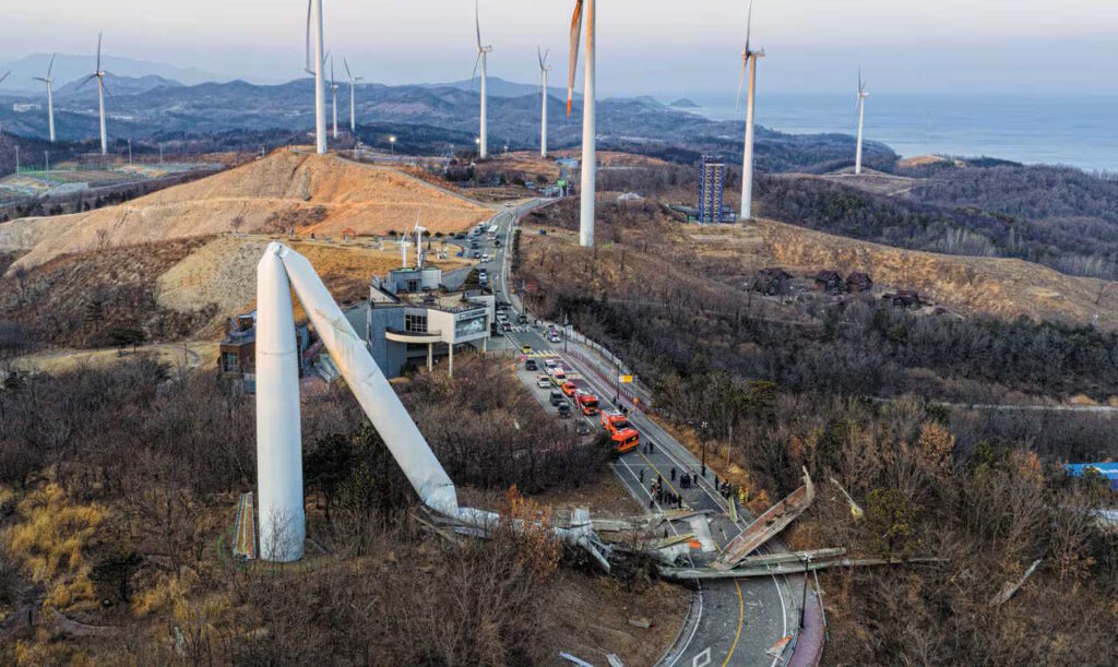
Two incidents at the same wind farm, seven weeks apart, tell a single engineering story that’s worth unpacking carefully. On February 2, 2026, an 80-meter Vestas turbine at the Yeongdeok wind farm in North Gyeongsang Province, South Korea, snapped roughly a third of the way up its tower and collapsed across a public road, in wind of only 5–7 m/s against a 20 m/s design tolerance. No one was hurt, though a passing vehicle reportedly missed the debris by seconds.
Video Link
Then, on March 23, a fire broke out in the blade of a neighboring turbine at the same complex while three maintenance workers were inside it, inspecting and repairing cracks in that very blade. All three died.
Read separately, these look like two unrelated accidents. Read together, with the engineering filled in, they’re the same failure mode arriving twice: an aging turbine fleet, running past its design fatigue life, being managed with the one tool available when there’s no continuous structural data — sending people inside the blade to look for cracks by hand.
1. What Actually Failed on February 2
The damaged unit, Turbine 21, had been in continuous operation since May 2005 — 21 years at the time of failure, one year past the roughly 20-year fatigue design life typical of utility-scale wind turbine blades. County officials reported that one blade tore apart during rotation, causing the turbine to lose balance and strike the steel tower, which then buckled at its midpoint. The turbine had passed its most recent safety inspection.
The low wind speed at failure (5–7 m/s, roughly a third of the design tolerance) is the detail that rules out an overload failure and points squarely at fatigue. A tower doesn’t buckle in light wind because the wind pushed too hard; it buckles because something inside the rotor changed catastrophically and suddenly, and the resulting dynamic load bore no resemblance to the quasi-static design load case the tower was engineered against.
2. The Physics of Losing a Blade Mid-Rotation
A healthy three-blade rotor is mass-balanced: each blade’s centrifugal force is canceled by the other two, spaced 120° apart, and the net rotating force at the hub is essentially zero. The moment one blade fails — whether it detaches entirely or loses a substantial outboard section — that cancellation stops working. The rotor instantly behaves like a rotating system with a large residual unbalance, producing a synchronous force at the rotor’s rotational frequency (called 1P in wind industry shorthand) governed by the classic rotating-unbalance relationship:
\[ F = m\, e\, \omega^{2} \]where \( m \) is the unbalanced mass, \( e \) is its distance from the rotor axis (roughly the blade’s center of mass location, typically well outboard given a tapered blade planform), and \( \omega \) is the rotor’s angular velocity.
To put a representative order of magnitude on this — using illustrative parameters typical of this turbine class rather than confirmed figures from the actual failed unit, since the investigation results aren’t public — a blade of this generation and length (roughly 40 m) might have a mass on the order of several tonnes, with its center of mass perhaps 15 m out from the hub, on a rotor turning at roughly 10–11 rpm (\( \omega \approx 1.1\, \mathrm{rad/s} \)). Plugging in \( m = 6000 \) kg and \( e = 15 \) m gives:
\[ F \approx (6000)(15)(1.1)^{2} \approx 1.1 \times 10^{5} \; \mathrm{N} \]— on the order of 110 kN, or about 11 tonnes-force, rotating at the 1P frequency and applied at the top of an 80-meter tower. The resulting bending moment at the tower base, simply as force times lever arm, is on the order of
\[ M \approx F \times h \approx (1.1 \times 10^{5})(80) \approx 9 \times 10^{6} \; \mathrm{N\cdot m} \]That’s a bending moment measured in meganewton-meters, arriving as a step change the instant the blade fails, layered on top of whatever moment the wind itself was already producing — and this is before accounting for the additional transient dynamic amplification that a sudden step load produces when it excites a structure’s natural bending modes, which for a tower this size and mass typically sit in a frequency range the turbine’s designers work hard to keep clear of both the 1P and blade-passing (3P) frequencies during normal, balanced operation. A sudden, severe imbalance doesn’t respect that clearance the way steady-state operation does. A tower designed against decades of ordinary aerodynamic thrust loading was never meant to absorb this kind of abrupt, large-amplitude dynamic input, and the light wind at the time of collapse becomes almost irrelevant once the actual driving force is understood to be the blade failure itself, not the wind.
3. Why the Blade Failed at 21 Years
Utility-scale wind turbine blades are fiberglass or carbon-fiber composite structures, designed to IEC 61400-1 fatigue life targets typically in the 20–25 year range, using Miner’s rule cumulative damage summation across the enormous number of load cycles a rotor accumulates over its life — a blade experiences roughly one full gravity-bending stress reversal per revolution, in addition to wind-turbulence-driven cyclic loading, multiplied out over hundreds of millions of cycles across two decades of continuous rotation. Composite fatigue behavior differs meaningfully from the metal fatigue curves most structural engineers cut their teeth on: matrix microcracking, fiber-matrix debonding, and delamination accumulate progressively and are considerably harder to detect from the outside than a single dominant crack front in a metal, right up until a critical flaw finally propagates to failure.
Turbine 21 wasn’t an outlier at this site — it’s the norm. The Yeongdeok/Changpo-ri wind farm, completed in January 2006, is South Korea’s oldest, and its 24 turbines account for 92.3% of the entire nation’s wind turbines older than 20 years. This is a fleet-aging problem, not an isolated component defect, and the county government has since called for dismantling the aging units altogether.
4. The Fatal Irony: Manual Inspection Is the Only Tool When There’s No Continuous Data
Seven weeks after the tower collapse, three contracted maintenance workers were inside the blade of neighboring Turbine 19 — also a Vestas 1.65 MW unit — specifically inspecting and repairing cracks when a fire broke out inside the blade. All three died.
This is the part of the story that deserves the most attention from a reliability-engineering standpoint. Manual blade crack inspection exists precisely because most of this generation of turbine has no continuous structural health monitoring instrumentation built in — no strain gauges, no fiber-optic sensing, no acoustic emission monitoring streaming data on blade condition between visits. The only way to know whether a known fatigue-prone composite structure has developed a dangerous crack is to send a person up into it and look, physically, with hand tools, often specifically because a crack has already been flagged as a concern — exactly the scenario underway on Turbine 19 when the fire started. The inspection method that exists to prevent a Turbine-21-style failure is itself a source of direct human risk, and in this case a fatal one.
5. What Continuous Monitoring Actually Changes
None of the monitoring technology available today eliminates the need for human access to a blade altogether — at some point, a physical repair still requires a technician inside the structure. What continuous instrumentation changes is the frequency and the context of that access: rather than periodic manual inspections on a fixed calendar interval, sensors embedded in or bonded to the blade (strain gauges, fiber Bragg grating fiber-optic strain sensing, or acoustic emission sensors tuned to detect the ultrasonic signature of matrix cracking and fiber breakage as it happens) can flag a developing defect between visits, target inspection to the specific blade and specific location where damage is actually accumulating, and give the technician sent up an actual picture of what they’re likely to find before they climb — rather than a blind, calendar-driven crack hunt across a blade that might be sound. This is precisely the argument for structural health monitoring I made in a recent post on the sensory-and-stethoscope era of machinery diagnostics: continuous instrumented monitoring doesn’t replace human judgment, it targets it, and it catches problems in the window between scheduled visits where the older methods are structurally blind by design.
Closing Thought
A 21-year-old composite blade failing one year past its design fatigue life, in wind a third of its design limit, producing a rotor imbalance large enough to buckle an 80-meter steel tower, is a clean textbook illustration of what happens when a structure quietly crosses its fatigue threshold with no instrumentation watching. That the very next chapter of this story is three fatalities during the manual inspection process meant to catch exactly that kind of defect is the sharper, harder lesson: for an aging fleet with no continuous structural data, the absence of instrumentation isn’t just a blind spot in a maintenance program. It’s a risk that eventually gets transferred directly onto the people sent to compensate for it.
References
- “80-meter wind turbine collapses on road in Yeongdeok,” The Korea Herald, February 3, 2026.
- “County chief calls for dismantling all wind turbines after back-to-back accidents,” The Korea Herald, March 24, 2026.
- “Wind Turbine Fire Kills 3,” ISSSource, citing Korea JoongAng Daily, March 2026.
- “Fire at Yeongdeok wind turbine; All 3 workers dead,” WindAction, citing Chosun Ilbo, March 2026.
- “Twenty-year-old wind turbine collapses, narrowly missing parked car,” reNews/reneweconomy.com.au, February 2026.
- IEC 61400-1, Wind Turbines — Part 1: Design Requirements, for turbine fatigue design life provisions.
- VibrationData blog, “Touch, Hearing, Stethoscopes, and Stroboscopes in Machinery Vibration Monitoring,” July 2026 — for the continuous-monitoring-versus-manual-inspection framing referenced above.
📌 Further Reading: This article is part of our Wind Turbine Vibration & Dynamics Engineering Guide. Visit the hub page for more case studies and analysis on turbine fatigue and rotor mechanics.
Looking for a deep dive on this topic? Explore our comprehensive guide and resource collection on the Residual Stress & Structural Integrity Hub.