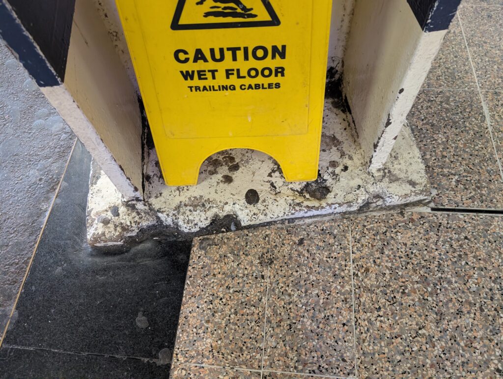
By Tom Irvine | Structural Integrity Series — Gatwick Airport Railway Station, United Kingdom
The photograph above was taken at Gatwick Airport Railway Station — the busiest airport rail station in the United Kingdom, serving both the Gatwick Express and Southern/Thameslink services with approximately 19 million passengers per year. The yellow wet floor sign warns of an immediate slip hazard, but it inadvertently frames a more serious long-term engineering problem: the deteriorating base of a structural column. Paint is delaminating in sheets. White crystalline deposits coat the surface. The grout or bedding mortar at the floor–column interface is crumbling and blackened with biological growth. Water pools at the base.
The irony is pointed. Gatwick station is a safety-critical rail infrastructure asset regulated by the Office of Rail and Road (ORR) and managed under Network Rail’s asset management framework — yet this column base, in a public concourse area carrying tens of thousands of passengers daily, displays textbook signs of long-term water infiltration and neglected maintenance. The wet floor sign addresses the symptom. The structural question is whether Network Rail’s periodic inspection regime is capturing the cause.
This is not a cosmetic issue. The column base — the interface between the vertical load-carrying element and its foundation — is one of the most structurally critical details in any building frame. Deterioration here compromises the boundary condition that every structural and dynamic analysis assumes to be intact.
1. What the Photograph Reveals
Several simultaneous degradation mechanisms are visible:
- Efflorescence — the white crystalline deposit coating the column base. Soluble calcium salts (primarily calcium carbonate, Ca CO₃, and calcium sulfate, CaSO₄) are carried to the surface by water migrating through the concrete or mortar, where they precipitate on evaporation. Efflorescence is a reliable indicator of sustained water infiltration through the substrate.
- Paint delamination — the coating system has lost adhesion to the substrate, forming blisters and peeling sheets. Osmotic pressure from moisture trapped beneath the paint film, combined with differential thermal expansion between the coating and substrate, drives progressive delamination. Once the coating fails, the substrate is exposed directly to the aggressive coastal environment.
- Bedding mortar deterioration — the grout or mortar at the column base–floor interface is visibly crumbling and darkened. This zone is subject to wetting-drying cycles, freeze-thaw cycling (30–50 cycles per year at Gatwick), and biological colonization (algae, mold — the black discoloration). The mortar’s compressive and bond strength are reduced.
- Standing water — pooling at the column base indicates either inadequate drainage detailing or a blocked drainage path. Sustained immersion dramatically accelerates all of the above mechanisms and adds hydrostatic pressure to the list of driving forces.
2. Efflorescence: The Chemistry of Water Migration
Efflorescence follows a three-step process:
- Water ingress — rainwater, groundwater, or condensation penetrates the concrete or mortar through capillary suction, microcracks, or poorly sealed joints
- Leaching — the water dissolves soluble salts from the cement matrix, primarily calcium hydroxide (Ca(OH)₂) from the hydration products of Portland cement
- Precipitation — as the water migrates to the surface and evaporates, the dissolved salts crystallize:
\[ \text{Ca(OH)}_2 + \text{CO}_2 \rightarrow \text{CaCO}_3 \downarrow + \text{H}_2\text{O} \]
The white deposit is calcium carbonate — the same compound as limestone and chalk. In coastal environments with sulfate-bearing groundwater or sea spray, calcium sulfate (gypsum, CaSO₄·2H₂O) also deposits, producing a harder, more adherent white crust.
Efflorescence itself is not directly structurally damaging, but it is an unambiguous indicator of ongoing water movement through the structural element. The water that deposits the salts is the same water that:
- Carries chloride ions to any embedded steel reinforcement, initiating corrosion
- Dissolves the calcium silicate hydrate (C-S-H) gel that gives concrete its strength — a process called leaching or decalcification
- Provides the electrolyte for galvanic and crevice corrosion at any embedded metal anchor or baseplate
The mass loss from leaching reduces the compressive strength of the affected concrete zone. For a leached depth \( d_l \), the effective compressive strength of the cross-section is reduced approximately as:
\[ f’_{c,eff} = f’_c \left(1 – \frac{2 d_l}{D}\right)^2 \]
where \( D \) is the column dimension. For a 300 mm square column with 20 mm of leached concrete on each face: the effective strength is reduced to approximately 64% of the original — a significant structural penalty from what appears to be surface discoloration.
3. The Column Base as a Structural Boundary Condition
In structural analysis, every column is modeled with a boundary condition at its base — fixed, pinned, or partially restrained (semi-rigid). The degree of fixity determines:
- The effective buckling length \( L_{eff} \) of the column
- The distribution of bending moments along the height
- The natural frequencies of the structure
- The seismic response and base shear distribution
For a column assumed fixed at the base, the Euler critical buckling load is:
\[ P_{cr} = \frac{\pi^2 EI}{(0.5 L)^2} = \frac{4\pi^2 EI}{L^2} \]
For a column with a pinned base, the critical load drops to:
\[ P_{cr} = \frac{\pi^2 EI}{L^2} \]
— exactly one quarter of the fixed-base value. If base deterioration degrades the connection from fixed toward pinned, buckling capacity is reduced by 75%. For a slender column under significant axial load, this progression from fixed to pinned boundary condition is not gradual and benign — it is potentially catastrophic.
3.1 Semi-Rigid Base Stiffness
The actual column base stiffness \( k_\theta \) (rotational, N·m/rad) lies between the pinned (\( k_\theta = 0 \)) and fixed (\( k_\theta = \infty \)) ideals. For a deteriorating base, \( k_\theta \) decreases as:
- Bedding mortar loses compressive and bond strength — reducing the bearing area transmitting moment to the foundation
- Grout voids develop — creating gaps that allow column rotation before contact is established
- Any embedded anchor bolts corrode — reducing their tensile capacity and the moment arm of the tension couple
The effective buckling length for a column with semi-rigid base stiffness \( k_\theta \) is:
\[ L_{eff} = L \sqrt{\frac{1}{1 + \frac{3EI}{k_\theta L}}}^{-1} \]
As \( k_\theta \rightarrow 0 \), \( L_{eff} \rightarrow 2L \) (pinned base). As \( k_\theta \rightarrow \infty \), \( L_{eff} \rightarrow 0.5L \) (fixed base). The transition between these limits is nonlinear and accelerates as deterioration progresses — small reductions in \( k_\theta \) at low stiffness have large effects on \( L_{eff} \).
4. Dynamic Implications: Natural Frequency and Seismic Response
The boundary condition at the column base directly controls the structure’s natural frequencies. For a cantilever column (fixed base, free top) with distributed mass, the fundamental natural frequency is:
\[ f_1 = \frac{1.875^2}{2\pi L^2} \sqrt{\frac{EI}{\rho A}} \]
For a pinned base (equivalent to a pinned-free column), the frequency drops by a factor of \( (1.875/\pi)^2 \approx 0.358 \) — the natural frequency falls to about 60% of the fixed-base value. This frequency shift has two serious consequences:
4.1 Resonance with New Excitation Sources
As the base deteriorates and \( f_1 \) drops, the column may move into resonance with excitation sources that were previously off-resonance:
- Pedestrian loading — human walking generates harmonics at 1–3 Hz; a softened base can bring a column into resonance with this everyday excitation
- HVAC equipment — fan and compressor units typically operate at 10–50 Hz; if a deteriorated base lowers a column’s frequency into this range, resonant amplification of HVAC-induced vibration can fatigue the remaining connection detail
- Wind-induced vortex shedding — the Strouhal frequency \( f_s = S_t U / D \) may coincide with the degraded natural frequency, causing lock-in and oscillatory amplification of wind loads
4.2 Dynamic Loading at a Railway Station
The UK is a low seismicity country (design PGA typically 0.02–0.05g), so seismic loading is not the primary dynamic concern. However, a busy railway station introduces dynamic excitation sources that are considerably more intense and structured than a typical building:
- Train-induced ground vibration — passing trains generate ground-borne vibration in the frequency range 4–250 Hz, transmitted through the track bed and station structure to columns and floor slabs. For Gatwick station, Gatwick Express (Class 387) and Southern/Thameslink services pass through at platform speeds of 15–40 mph. The dominant excitation frequencies correspond to rail corrugation wavelengths, wheel flats, and bogie pass frequencies. A column with a degraded base stiffness has a lower natural frequency and potentially increased dynamic amplification factor (DAF) for train-induced excitation.
- Crowd-induced loading — approximately 19 million passengers per year pass through Gatwick station. Synchronized pedestrian movement generates rhythmic loading at 1.6–2.4 Hz (walking pace). The Highways England/Network Rail design standard for footbridges and station structures (BD 37/01, now superseded by BS EN 1991-2) requires dynamic assessment when the fundamental frequency of a structure falls below 5 Hz — a threshold that a deteriorated column base may approach.
- Trolley and luggage cart impact — passenger luggage trolleys and station service vehicles impose repeated low-level impact loads at column bases. The deteriorated mortar zone offers reduced resistance to these eccentric impacts, and each impact event provides an incremental crack propagation increment at the existing damage front.
- Roof structure thermal cycling — Gatwick station’s large-span roof imposes cyclic lateral forces at column tops through thermal expansion and contraction (UK temperature range approximately −5°C to +35°C, giving ΔT ≈ 40°C seasonal range). For a steel roof truss of 50 m span, the thermal displacement is \( \delta = \alpha \Delta T L = 12\times10^{-6} \times 40 \times 50 \approx 24 \) mm — a significant cyclic lateral displacement imposed directly on the column top, fatigue-cycling the deteriorated base connection.
- Wind loading — BS EN 1991-1-4 governs; Gatwick’s suburban exposure gives a basic wind velocity of ~23 m/s. Station structures with large open facades are particularly susceptible to wind-induced pressure fluctuations at column bases.
The train-induced vibration deserves particular attention. The vibration velocity at the column base from passing trains can be estimated using the stress-velocity relationship:
\[ \sigma = \rho c V \]
where \( \rho \) is the concrete density (2400 kg/m³), \( c \) is the longitudinal wave speed (\( \sqrt{E/\rho} \approx 3500 \) m/s for concrete), and \( V \) is the particle velocity at the column base. For a measured peak particle velocity of 5 mm/s from a passing train — typical for a station platform column — the induced dynamic stress is:
\[ \sigma = 2400 \times 3500 \times 0.005 = 42{,}000 \text{ Pa} = 0.042 \text{ MPa} \]
This is well below concrete strength in isolation, but applied cyclically at 19 million passenger journeys per year — with associated train movements numbering in the hundreds of thousands — the cumulative fatigue loading on a pre-cracked, mortar-voided column base is non-trivial. The Fatigue Damage Spectrum (FDS) methodology, available in the VibrationData toolbox, provides the framework for assessing cumulative fatigue damage from broadband vibration environments of this type.
A softened base increases lateral drift under all dynamic loading. BS EN 1992-1-1 (Eurocode 2) limits second-order \( P\text{-}\Delta \) effects, which become significant when lateral drift at column top exceeds \( L/300 \). A column transitioning from fixed to pinned base can exceed this limit under combined crowd, train, and wind loading — triggering secondary moment amplification that further stresses the deteriorated base zone.
5. Moisture at the Base: Freeze-Thaw, De-icing Salts, and the Railway Environment
Gatwick’s temperate maritime climate (mean annual temperature ~11°C, regularly cycling through 0°C in winter) subjects this column base to the full freeze-thaw damage mechanism — far more aggressive than a tropical coastal climate. Water in saturated concrete pores expands by approximately 9% on freezing, generating internal hydraulic pressures that can exceed 200 MPa in a fully confined pore — far beyond concrete’s tensile strength of 3–5 MPa. Each freeze-thaw cycle propagates microcracks, increasing porosity and accelerating subsequent water ingress in a self-reinforcing deterioration cycle.
The number of freeze-thaw cycles per year at Gatwick is approximately 30–50 — sufficient to produce measurable surface scaling within 5–10 years on inadequately air-entrained or porous concrete. The UK Highways Agency’s design standard for concrete in freeze-thaw exposure (BD 57/01) specifies a minimum air entrainment of 4–6% for concrete subject to de-icing salts — a requirement that may not have been applied to internal station column bases.
The railway station environment adds a particularly aggressive chemical cocktail: track de-icing salts, third rail leakage, and rail contamination. Network Rail applies sodium chloride and calcium chloride solutions to running rails and the 750V DC Southern Region conductor rail during winter. These solutions aerosolize from passing trains and settle throughout the station concourse. Passengers track additional chloride grit in from external pavements. Chloride ingress from these combined sources is one of the primary causes of premature reinforcement corrosion in UK rail infrastructure, and is far more aggressive than natural exposure because:
- Chloride concentrations are high — rail de-icing solution application rates deliver concentrated chloride to station floors, pooling preferentially at column bases in re-entrant corners
- Stray current corrosion — leakage currents from the 750V DC third rail system can electrochemically accelerate corrosion of embedded steel anchors and reinforcement at the column base, independently of chloride concentration
- Brake dust and diesel particulates — hygroscopic deposits from train operations retain moisture at column bases, creating a persistently wet microenvironment even during dry weather periods
- Wet-dry cycling from foot traffic and cleaning operations concentrates chloride at the concrete surface by capillary suction followed by evaporation — the same mechanism responsible for reinforcement corrosion in road bridge decks subject to de-icing salt spray
Additionally, salt crystallization pressure from both chloride salts and sulfates operates in the pore space:
\[ p_{cryst} = \frac{\nu RT}{V_m} \ln\left(\frac{c}{c_s}\right) \]
where \( \nu \) is the number of ions, \( R \) is the gas constant, \( T \) is temperature (K), \( V_m \) is the molar volume of the salt crystal, \( c \) is the actual ion concentration, and \( c_s \) is the saturation concentration. For sodium chloride at high concentration, \( p_{cryst} \) can reach 10–35 MPa — exceeding concrete tensile strength and driving progressive microcracking as a parallel mechanism to freeze-thaw. This is subflorescence, producing surface scaling and spalling.
The black discoloration at the mortar base is consistent with biological colonization — algae, mold, and bacteria that thrive in persistently damp, low-light column base zones in heated station concourses. The warm, humid microclimate at floor level in a busy rail station — high footfall, frequent cleaning with water, poor drainage — is ideal for biological growth, which produces organic acids that attack the cement matrix, lower local pH, and directly accelerate carbonation.
6. Carbonation: The Long-Term Threat to Reinforcement
Concrete’s alkalinity (pH 12.5–13.5) normally passivates embedded steel reinforcement, forming a dense iron oxide film that prevents active corrosion. Carbonation — the reaction of atmospheric CO₂ with calcium hydroxide in the cement paste — neutralizes this alkalinity:
\[ \text{Ca(OH)}_2 + \text{CO}_2 \rightarrow \text{CaCO}_3 + \text{H}_2\text{O} \]
The carbonation front advances inward from the surface at a rate approximately proportional to \( \sqrt{t} \):
\[ d_c = k_c \sqrt{t} \]
where \( d_c \) is carbonation depth (mm), \( t \) is time (years), and \( k_c \) is the carbonation coefficient (typically 1–5 mm/year^0.5 for normal concrete, higher for permeable or porous concrete). The UK’s relatively high atmospheric CO₂ levels in enclosed public spaces — busy railway station concourses with high occupancy and diesel traction can have CO₂ concentrations of 800–2000 ppm, versus the outdoor average of ~420 ppm — accelerate carbonation rates indoors compared to external structures. Diesel exhaust from Thameslink Class 700 units operating in diesel mode adds directly to local CO₂ and NOₓ concentrations, further accelerating the acid-base neutralisation of the cement matrix. When the carbonation front reaches the reinforcement depth \( c \) (cover), depassivation occurs and active corrosion initiates — even without chloride ingress. The time to corrosion initiation is:
\[ t_{init} = \left(\frac{c}{k_c}\right)^2 \]
For 20 mm cover and \( k_c = 3 \) mm/year^0.5: \( t_{init} = (20/3)^2 \approx 44 \) years under normal conditions. For the deteriorated, paint-failed, moisture-saturated and de-icing salt-contaminated base visible in the photograph, \( k_c \) may be considerably higher — carbonation could be reaching reinforcement depth in 10–20 years. The concurrent chloride ingress from terminal floor de-icing salt creates a dual attack: carbonation destroys the passive film, and chlorides drive the active corrosion current once depassivation occurs. The combination is significantly more aggressive than either mechanism alone. UK Highways Agency standard BD 57/01 and the more recent CS 454 (formerly BD 57) address carbonation and chloride-induced corrosion in highway structures — the same framework applies to airport infrastructure.
7. Vibration-Based Structural Health Monitoring
The progression of column base deterioration — from intact fixed condition through semi-rigid toward pinned — produces measurable changes in the structure’s dynamic response. This is the basis of vibration-based structural health monitoring (SHM): tracking changes in natural frequencies, mode shapes, and damping ratios to detect and localize structural damage without destructive testing.
The relationship between structural stiffness degradation and natural frequency shift is direct. For a single-degree-of-freedom (SDOF) analogy of the column:
\[ f_n = \frac{1}{2\pi}\sqrt{\frac{k}{m}} \]
A 50% reduction in base stiffness \( k \) produces a \( 1 – \sqrt{0.5} \approx 29\% \) reduction in natural frequency — a readily detectable change with even a modest accelerometer and FFT analyzer. The VibrationData toolbox provides the spectral analysis tools needed for ambient vibration-based SHM: power spectral density estimation, frequency response function calculation, and system identification via the rational fraction polynomial method.
For the column photographed, a simple tap test with a calibrated impact hammer and a single accelerometer at the column top would reveal the current fundamental frequency. Comparison against the as-built design frequency (calculable from the column geometry and assumed boundary conditions) would immediately quantify the degree of base stiffness degradation — giving the building owner an objective metric rather than a visual inspection opinion.
8. What Should Have Been Done: Detailing for Durability
The deterioration visible in the photograph is the consequence of inadequate detailing at a high-risk location — the column base, where water pools, salt deposits, and biological growth converge. The following measures would have prevented it:
- Proper drainage slope — floor finish sloped at minimum 1:80 away from the column base per BS 8204 (screeds, bases and in-situ floorings), preventing water pooling. The standing water visible in the photograph indicates zero or negative drainage slope at this location — a basic construction defect.
- Waterproof membrane at the base interface — a polyurethane or crystalline waterproofing membrane at the column–floor joint per BS 8102 (protection of below-ground structures against water from the ground), preventing capillary water rise into the column base.
- High-quality coating system — an epoxy or polyurethane coating rated for internal wet environments with de-icing salt exposure (equivalent to C3–C4 category per ISO 12944) rather than standard decorative paint. The delaminated paint visible is clearly not a waterproof protective system.
- Cove detail at the floor–column junction — a rounded cove of waterproof render or sealant at the base angle prevents water ponding in the re-entrant corner. This is standard specification in UK airport terminal construction and industrial flooring contracts.
- Air-entrained concrete mix design — for column bases subject to freeze-thaw and de-icing salt exposure, BS EN 206 Exposure Class XF4 (highly saturated concrete with de-icing agents) requires minimum 4% air entrainment and w/c ≤ 0.45.
- Sacrificial anode or cathodic protection for any embedded steel anchor bolts — zinc anodes or an impressed current system per BS EN ISO 12696.
- Routine inspection under Network Rail’s asset management framework — UK railway infrastructure is subject to periodic structural inspection under Network Rail’s Structures Management Procedure (NR/SP/CIV/017) and the ORR’s regulatory oversight. Station structures are classified as Schedule 8 assets requiring periodic condition assessment. Column base efflorescence mapping and carbonation depth testing (phenolphthalein indicator test) should be included on a 3–5 year cycle. The condition visible in this photograph is consistent with a column base that has not received a detailed inspection within the required maintenance cycle — a finding that should be reported to the relevant Network Rail Route Asset Manager.
9. Repair Approach
For the column base as photographed, the repair sequence mirrors the approach for the railing bracket described in the companion post, adapted for a compression-dominated element:
- Remove all deteriorated material — mechanically remove loose paint, efflorescence, and crumbling mortar to a sound substrate. Wire brush or needle gun to bright surface.
- Phenolphthalein carbonation test — drill a small hole, spray indicator on the fresh concrete face. Pink = alkaline (non-carbonated). Colorless = carbonated. Map the carbonation front depth.
- Apply corrosion inhibitor — if carbonation has reached or is approaching reinforcement depth, apply a penetrating amino-alcohol inhibitor by brush to delay further corrosion initiation.
- Re-profile with polymer-modified repair mortar — build up lost section using a class R4 structural repair mortar (EN 1504-3) bonded with epoxy primer. Do not use plain sand-cement mortar — its shrinkage will cause delamination.
- Form the cove detail — tool a 40 mm radius cove at the column–floor interface while the repair mortar is still plastic.
- Apply waterproof coating system — minimum two coats polyurethane or cementitious waterproofing over the entire column base to 300 mm above finished floor level.
- Address drainage — recut the floor finish to provide positive drainage away from the column base. If floor level prevents this, install a small perimeter drain channel.
- Fit tell-tale crack gauge — if any cracking is present at the base, fit a crack gauge to monitor for ongoing movement before and after repair.
Summary
A wet floor sign and a deteriorating column base, photographed in passing, contain the full narrative of concrete durability engineering:
- Efflorescence signals sustained water migration through the structural element, carrying chlorides to reinforcement and leaching calcium from the cement matrix
- Paint delamination exposes the substrate to direct moisture and salt attack, accelerating carbonation and biological colonization
- Bedding mortar deterioration at the column–floor interface degrades the rotational stiffness of the base boundary condition
- Loss of base fixity reduces buckling capacity by up to 75%, lowers natural frequency, and increases seismic drift — three independent structural consequences of what appears to be a maintenance issue
- Vibration-based SHM — a tap test and FFT — can quantify base stiffness degradation non-destructively and provide an objective metric for repair urgency
- All of this was preventable with correct drainage detailing, a waterproof membrane at the base interface, and a suitable coating system at initial construction
The wet floor sign warns of an immediate slip hazard. The structural engineer’s concern is the slow-motion hazard accumulating beneath it.
Part of the VibrationData Structural Integrity Series — Gatwick Airport Railway Station, United Kingdom, July 2026. Related posts: Corrosion-Induced Concrete Cracking — Mechanisms and Mitigation; Vibration-Based Structural Health Monitoring; ASCE 7-22 Seismic Equipment Anchorage.
References and further reading at vibrationdata.com.