By Tom Irvine
The spruce soundboard of a concert grand piano and the sheet-steel housing of an industrial gearbox have more in common than their outward appearances suggest. Both are thin panels driven into vibration by an internal source. Both radiate sound into the surrounding air. Both are engineered — intentionally in one case, reluctantly in the other — to control the amplitude, frequency content, and directivity of that radiation. Understanding the physics that makes a Steinway sing is the same physics that explains why a gearbox howls, and the same physics that guides the engineer trying to silence it.
1. The Soundboard: A Precision Sound Radiator
The soundboard is the primary sound-radiating surface of every major acoustic instrument in the Western tradition — piano, violin, guitar, cello, lute, harpsichord. Its function is to transform the high-impedance, small-amplitude vibration of a string (or reed, or plucked quill) into low-impedance, large-amplitude pressure waves in air. Without the soundboard, the string radiates almost no sound — its diameter is far too small to couple efficiently to the acoustic medium.
1.1 Impedance Matching: Why the Soundboard Exists
The fundamental problem is acoustic impedance mismatch. The characteristic impedance of a medium is:
\[ Z = \rho c \]
where \( \rho \) is density and \( c \) is sound speed. For air: \( Z_{air} = 1.21 \times 343 \approx 415 \) Pa·s/m. For steel: \( Z_{steel} \approx 7800 \times 5100 \approx 40 \times 10^6 \) Pa·s/m. The impedance ratio is approximately 100,000:1 — a string vibrating in air is essentially acoustically invisible. The soundboard acts as a mechanical transformer, presenting a large radiating area to the air while being mechanically driven by the string at a single contact point.
The power radiated by a vibrating panel into a fluid half-space is:
\[ W_{rad} = \rho_0 c_0 \sigma_{rad} \langle v^2 \rangle S \]
where \( \rho_0 c_0 \) is the specific acoustic impedance of air (415 Pa·s/m), \( \sigma_{rad} \) is the radiation efficiency (dimensionless, 0 to 1+), \( \langle v^2 \rangle \) is the mean-square surface velocity averaged over the panel, and \( S \) is the panel area. This single equation governs both the concert piano and the noisy gearbox — the physics is identical.
1.2 Radiation Efficiency \( \sigma_{rad} \)
The radiation efficiency is the most important parameter in panel acoustics. It depends critically on the ratio of the panel’s bending wave speed \( c_B \) to the speed of sound in air \( c_0 \):
\[ c_B = \left(\frac{\omega^2 E h^2}{12 \rho (1-\nu^2)}\right)^{1/4} \]
where \( \omega \) is angular frequency, \( E \) is Young’s modulus, \( h \) is panel thickness, \( \rho \) is panel density, and \( \nu \) is Poisson’s ratio. The critical frequency — also called the coincidence frequency — occurs when \( c_B = c_0 \):
\[ f_c = \frac{c_0^2}{2\pi h} \sqrt{\frac{12\rho(1-\nu^2)}{E}} \]
The radiation efficiency behavior relative to \( f_c \) is:
| Frequency Range | \(\sigma_{rad}\) | Physical Interpretation |
|---|---|---|
| \( f \ll f_c \) | \( \ll 1 \) | Panel waves too slow; poor coupling to air |
| \( f \approx f_c \) | \( \gg 1 \) (peak) | Coincidence: bending waves match acoustic wavelength; maximum radiation |
| \( f \gg f_c \) | \( \approx 1 \) | Above coincidence; efficient radiation |
The critical frequency for common panel materials at 1 mm thickness:
| Material | \( f_c \) at 1 mm (Hz) | Notes |
|---|---|---|
| Spruce (along grain) | ~1,200 | Piano/guitar soundboard material |
| Spruce (across grain) | ~8,000 | Anisotropic — by design |
| Steel | ~12,000 | Scales as 1/h, so 2 mm → 6,000 Hz |
| Aluminum | ~12,500 | Similar to steel |
| Glass | ~12,700 | High stiffness, high density |
Note that \( f_c \) scales as \( 1/h \) — doubling panel thickness halves the critical frequency. For a 3 mm steel gearbox panel, \( f_c \approx 4,000 \) Hz — squarely in the most sensitive region of human hearing (2–5 kHz). This is not a coincidence; it is why steel machinery housings are such effective sound radiators in the most annoying frequency range.
2. The Piano Soundboard: Engineering the Radiation
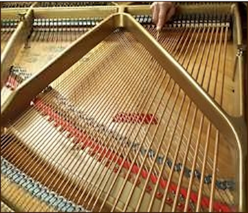
The piano soundboard is arguably the most acoustically engineered wooden structure ever built. A concert grand soundboard (Steinway Model D) is a 8–9 mm thick panel of quarter-sawn Sitka spruce, approximately 1.5 m × 1.0 m, stiffened by a system of ribs running perpendicular to the grain direction.
2.1 Material Anisotropy as Acoustic Design
Sitka spruce (\( Picea sitchensis \)) has a remarkable combination of properties for a soundboard material:
| Property | Along Grain | Across Grain |
|---|---|---|
| Young’s Modulus | ~11–14 GPa | ~0.5–1.0 GPa |
| Density | ~400–450 kg/m³ | |
| Sound speed \(c = \sqrt{E/\rho}\) | ~5,000 m/s | ~1,100 m/s |
| Specific modulus \(E/\rho\) | ~30 GPa·cm³/g | ~1.5 GPa·cm³/g |
The along-grain specific modulus of spruce is among the highest of any material — comparable to carbon fiber — while the density is extremely low. This gives spruce an exceptional acoustic efficiency figure of merit:
\[ Q_{acoustic} = \frac{c_{longitudinal}}{\rho} = \frac{\sqrt{E/\rho}}{\rho} \propto \frac{E^{1/2}}{\rho^{3/2}} \]
The extreme anisotropy (stiffness ratio ~15:1 along vs. across grain) allows the soundboard to transmit vibration efficiently along the grain (coupling the string force to the full panel area) while being compliant across the grain (providing the flexibility needed to move air). The ribs run across the grain, locally increasing cross-grain stiffness and controlling the modal density and mode shapes.
2.2 Modal Analysis of the Soundboard
The soundboard’s vibration at any frequency is a superposition of its structural modes. The natural frequencies of a simply-supported orthotropic panel are:
\[ f_{mn} = \frac{\pi}{2} \sqrt{\frac{D_x}{\rho h}} \left(\frac{m}{L_x}\right)^2 + 2\sqrt{\frac{D_{xy}}{\rho h}} \left(\frac{m}{L_x}\right)\left(\frac{n}{L_y}\right) + \sqrt{\frac{D_y}{\rho h}} \left(\frac{n}{L_y}\right)^2 \]
where \( D_x = E_x h^3 / 12(1-\nu_{xy}\nu_{yx}) \) and \( D_y \) are the bending stiffnesses in the two principal directions, and \( m, n \) are the half-wave mode indices. The rib pattern of the piano soundboard is designed to raise the cross-grain stiffness \( D_y \), increasing modal frequencies in the mid-range and smoothing the modal density across the piano’s frequency range (27.5 Hz to 4,186 Hz).
A critical design goal is even modal density — approximately equal numbers of modes per octave across the playing range. Regions of sparse modal density produce “dead” notes where the soundboard fails to respond efficiently; regions of excessive modal density produce tonal colorations and wolf notes. Voicing the piano involves mechanical adjustment of the hammer felt hardness to selectively excite different modal groups.
2.3 The Bridge: Coupling Force to Panel
The bridge transmits string force to the soundboard. From a structural dynamics perspective, it acts as a mechanical impedance transformer. The driving point impedance of the soundboard at the bridge contact must be matched to the string’s characteristic impedance for efficient energy transfer:
\[ Z_{string} = \sqrt{T \cdot m_L} \]
where \( T \) is string tension and \( m_L \) is mass per unit length. For a piano bass string at 800 N tension: \( Z_{string} \approx \sqrt{800 \times 0.10} \approx 9 \) N·s/m. If the bridge impedance is too high (stiff soundboard), energy stays in the string and the note sustains too long with low volume. Too low (compliant soundboard), and energy transfers quickly — loud initial attack but rapid decay. The luthier’s art is balancing these competing demands across a five-octave range.
3. The Violin: Helmholtz Resonance and the f-Holes
The violin adds an additional acoustic element absent from the piano: the air cavity resonance. The f-holes are not decorative — they are the aperture of a Helmholtz resonator formed by the instrument body cavity. The Helmholtz resonance frequency is:
\[ f_H = \frac{c_0}{2\pi} \sqrt{\frac{A}{V L_{eff}}} \]
where \( A \) is the total f-hole area, \( V \) is the internal cavity volume, and \( L_{eff} \) is the effective length of the f-hole neck (including end correction). For a typical violin: \( f_H \approx 270\text{–}290 \) Hz, coinciding with the open D string (293 Hz) — deliberately tuned by the maker to reinforce the fundamental of the open D and enhance the instrument’s projection in this register.
The violin soundboard (top plate) and back plate have distinct modal structures. The critical modes for violin acoustics are:
- B1- mode (~460 Hz): first bending mode of the top plate; primary radiator for the G-D string range
- B1+ mode (~530 Hz): coupled top-back bending; reinforces A string fundamental
- A0 mode: the Helmholtz air resonance (~270 Hz)
- A1 mode: first longitudinal air mode (~475 Hz)
The bass bar (a spruce strut glued inside the top plate beneath the bass string foot of the bridge) and the soundpost (a spruce dowel connecting top to back under the treble foot) both serve dual structural and acoustic functions — modifying the impedance and mode shapes of the coupled system. The soundpost, in particular, creates a mechanical coupling between top and back plates that fundamentally changes the radiation pattern, making the violin a dipole radiator at low frequencies rather than a monopole.
4. The Guitar: Bracing Patterns as Modal Engineering
The acoustic guitar soundboard faces a different challenge from the piano: it must radiate efficiently from 82 Hz (low E string) to beyond 5,000 Hz (harmonics of the high E), using a single spruce or cedar panel approximately 2.5 mm thick. The bracing pattern — the arrangement of spruce struts glued to the inner face of the soundboard — is the primary design variable.
The two dominant bracing philosophies represent different acoustic tradeoffs:
| Bracing Type | Stiffness Distribution | Acoustic Character |
|---|---|---|
| X-brace (Martin, Gibson) | Symmetric; high cross-brace stiffness | Balanced projection; suited to steel strings |
| Fan brace (Torres, classical) | Radial along grain; low cross stiffness | Rich, complex tone; suited to gut/nylon |
| Ladder brace (pre-1930s) | Uniform cross-grain reinforcement | Strong fundamental; limited high-frequency response |
| Scalloped X-brace | Locally reduced brace mass | Enhanced bass response; increased flexibility |
The scalloping of X-braces — routing material from the center of each brace to reduce mass while maintaining edge stiffness — is equivalent in structural terms to a tapered beam: the bending stiffness \( EI \) is maintained at the clamped ends while the effective mass is reduced, lowering modal frequencies and increasing the panel’s low-frequency response. This is the acoustic version of topology optimization.
5. The Direct Analogy: Metal Housing of Machinery
Every principle governing musical soundboards applies, in reverse, to the problem of noise radiation from machinery housings. The goal is identical — predict and control the sound power radiated by a vibrating panel — but the engineering objective is opposite: minimize radiation rather than maximize it.
5.1 The Gearbox as an Involuntary Soundboard
A gearbox housing is driven by gear mesh forces at the gear mesh frequency and its harmonics:
\[ f_{mesh} = N_{teeth} \times RPM / 60 \]
These forces transmit through the bearing housings to the case walls, exciting structural modes of the steel panels. The radiated sound power is again:
\[ W_{rad} = \rho_0 c_0 \sigma_{rad}(f) \langle v^2 \rangle S \]
For a typical gearbox with 3 mm steel walls, the critical frequency \( f_c \approx 4,000 \) Hz coincides with both the peak of human hearing sensitivity (A-weighting maximum) and often with gear mesh harmonics from high-speed gear stages. The result is that steel gearbox housings are extraordinarily efficient sound radiators in precisely the most perceptible frequency range — the acoustic engineer’s nightmare, and the instrument maker’s physics applied without intent.
5.2 Sound Power Level Prediction
The sound power level (SWL) radiated by a machine housing panel is:
\[ L_W = L_v + 10\log_{10}(\sigma_{rad}) + 10\log_{10}(S) + 10\log_{10}\left(\frac{\rho_0 c_0}{W_{ref}}\right) \]
where \( L_v = 10\log_{10}(\langle v^2 \rangle / v_{ref}^2) \) is the vibration velocity level (dB re \( 10^{-9} \) m/s) and \( W_{ref} = 10^{-12} \) W. This is the fundamental equation connecting a vibration measurement (accelerometer or laser Doppler vibrometer on the housing surface) to an acoustic prediction. It is the basis of the ISO 3744/3746 sound power measurement standards used for machinery noise rating.
5.3 Noise Control Strategies — Lessons from Instrument Making
The instrument maker’s art, reversed, provides the engineering toolkit for machinery noise reduction:
Strategy 1: Raise or Lower the Critical Frequency
The instrument maker chooses spruce because its low critical frequency (for its thickness) keeps \( \sigma_{rad} \) high across the playing range. The machinery noise engineer does the opposite:
- Increase panel thickness — \( f_c \propto 1/h \); doubling thickness halves \( f_c \), pushing it below the dominant excitation frequencies and reducing \( \sigma_{rad} \) in the critical band. This is mass-law noise control.
- Use constrained layer damping (CLD) — a viscoelastic layer bonded between two steel skins. At coincidence, the CLD dissipates energy before it can be radiated, reducing the \( \sigma_{rad} \) peak without changing \( f_c \).
- Use ribbing strategically — just as guitar bracing raises certain modal frequencies, welded ribs on a machine housing can move structural resonances away from gear mesh excitation frequencies. However, ribs also increase the panel’s radiation efficiency above \( f_c \), so placement must be optimized.
Strategy 2: Reduce Panel Velocity \( \langle v^2 \rangle \)
Reducing the vibration at source — equivalent to detaching the string from the soundboard — is the most effective approach:
- Vibration isolation mounts between the gear/bearing assembly and the housing wall — the equivalent of replacing the rigid bridge contact with an isolating elastomer layer
- Dynamic vibration absorbers (DVAs) tuned to the gear mesh frequency — attached to housing panels, they act as tuned mass dampers, reducing panel velocity at the target frequency
- Active vibration control using piezoelectric actuators bonded to housing panels — analogous to the active noise cancellation in headphones, but applied structurally
Strategy 3: Reduce Radiation Efficiency Directly
Acoustic baffles, enclosures, and absorptive linings reduce the coupling between the vibrating surface and the far field:
- Partial enclosures — wrapping the gearbox housing with an absorptive acoustic enclosure; the transmission loss of the enclosure wall must exceed \( 20\log_{10}(\sigma_{rad}) \) to be effective
- Surface acoustic impedance modification — applying sprayed-on or adhesive damping treatments (e.g. Aquaplas, Dynavin) to increase loss factor \( \eta \), reducing the peak \( \sigma_{rad} \) at coincidence
- Panel perforation — strategically perforating housing panels reduces their radiation efficiency below coincidence (perforated panels radiate less efficiently than solid panels of the same mass)
5.4 The Loss Factor: Damping in Instruments vs. Machinery
The structural loss factor \( \eta \) controls the amplitude of resonant response and is directly related to the reverberation time of the panel:
\[ \eta = \frac{2.2}{f \cdot T_{60}} \]
For a piano soundboard, \( \eta \approx 0.01\text{–}0.03 \) — low damping is intentional, allowing notes to sustain. For a gearbox housing, \( \eta \approx 0.001\text{–}0.005 \) for bare steel — the low damping is the problem. Constrained layer damping treatments can raise \( \eta \) to 0.05–0.3 in the target frequency range, reducing resonant velocities by 15–30 dB and bringing corresponding reductions in radiated sound power.
This is the fundamental irony: the luthier spends a career developing techniques to achieve the lowest possible damping in a wooden panel, while the acoustical engineer spends a career trying to achieve the highest possible damping in a steel one.
6. Structural Intensity: Mapping Energy Flow
One of the most powerful modern tools for both instrument acoustics and machinery noise is structural intensity (SI) — the vector field describing the flow of vibrational energy through a structure. The structural intensity is:
\[ \mathbf{I}_s = -\frac{1}{2} \text{Re}\left[\boldsymbol{\sigma} \cdot \mathbf{v}^*\right] \]
where \( \boldsymbol{\sigma} \) is the stress tensor and \( \mathbf{v}^* \) is the complex conjugate of the velocity vector. SI maps show energy flowing from sources (string bridge contact in a guitar; bearing housing in a gearbox) through the structure toward the radiating surfaces. In instruments, SI maps reveal how efficiently the bridge distributes energy across the soundboard. In machinery, they identify the primary energy transmission paths from the noise source to the radiating panels — guiding placement of damping treatments and isolation mounts for maximum noise reduction with minimum added mass.
7. Numerical Methods: FEA and BEM
Modern instrument acoustics and machinery noise analysis both rely on coupled structural-acoustic simulation:
- Finite Element Analysis (FEA) — models the structural vibration of the soundboard or housing panel; extracts natural frequencies, mode shapes, and forced response \( v(\mathbf{x}, \omega) \)
- Boundary Element Method (BEM) — uses the panel velocity distribution from FEA as a boundary condition to solve the exterior acoustic Helmholtz equation, predicting radiated sound pressure in the far field
- Statistical Energy Analysis (SEA) — applicable at high frequencies where modal density is high; models energy flow between coupled subsystems (gear → housing panel → acoustic cavity → far field) using power balance equations
The VibrationData BEM toolkit (covered in previous posts) implements the pulsating sphere and oscillating sphere benchmark solutions, and the sound-excited panel modal decomposition — all of which are directly applicable to both instrument acoustics and machinery housing noise prediction.
Summary
The physics of sound radiation from vibrating panels is universal. The concert grand piano, the Cremonese violin, and the industrial gearbox are all governed by the same four parameters: panel area, mean-square velocity, radiation efficiency, and acoustic impedance of air. The instrument maker exploits these relationships over centuries of empirical refinement to maximize the transfer of mechanical energy into audible sound. The machinery acoustician applies the same relationships in reverse, using modern simulation tools to minimize unwanted radiation.
Key takeaways for the machinery noise engineer:
- Steel housing panels with \( h \approx 2\text{–}4 \) mm have critical frequencies of 3,000–6,000 Hz — coinciding with peak human hearing sensitivity and common gear mesh harmonics
- Radiated sound power is proportional to \( \sigma_{rad} \langle v^2 \rangle S \) — all three terms must be addressed for effective noise reduction
- Constrained layer damping, vibration isolation, and ribbing geometry are the primary design levers — the same variables that the luthier manipulates to shape tonal character
- Structural intensity mapping identifies energy flow paths and guides optimal treatment placement
- The loss factor \( \eta \) is the key material parameter: instruments want it low, machines want it high
The next time you hear a gearbox whine, you are listening to an involuntary musical instrument — one whose maker never intended it to sing, but whose physics ensures that it does.
Related posts: BEM Acoustics — Pulsating and Oscillating Sphere Benchmarks; Sound-Excited Panel Modal Decomposition; Acoustics Fundamentals; Piping Vibration and Acoustic Fundamentals. References and further reading at vibrationdata.com.