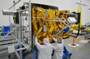
A good question came up recently regarding the practical design of a satellite bus panel for low random vibration response. The concern was not simply whether the panel is strong enough, but whether the panel can be designed so that mounted components see a lower acceleration environment during launch and operations.
That distinction is crucial. Strength design and vibration environment control are related, but they are not the same problem.
A satellite bus panel may have ample static strength margin and still produce high dynamic amplification at a component mounting location. Conversely, a panel with carefully placed modes, adequate damping, and thoughtful component layout can significantly reduce the component-level $G_{\text{RMS}}$ response.
The following guide outlines the practical engineering rules of thumb for controlling this environment.
Fundamental Frequency Is the Key Lever
The single most powerful design variable is usually the panel’s fundamental frequency. For a lightly damped, base-excited structure responding to a random vibration input, the peak resonant acceleration response can often be estimated using Miles’ Equation:
$$\ddot{x}_{\text{rms}} \approx \sqrt{\frac{\pi}{2} f_n Q W(f_n)}$$
where:
$f_n$ = natural frequency (Hz)
$Q$ = dynamic amplification factor
$W(f_n)$ = input acceleration Power Spectral Density (PSD) level at resonance ($\text{G}^2/\text{Hz}$)
This equation is an approximation, but it is highly valuable for preliminary design. It shows that the response depends on three primary vectors: the natural frequency of the panel, the amplification factor ($Q$), and the PSD level at that resonant frequency.
A common first instinct is to say, “Make the panel frequency lower to reduce $G_{\text{RMS}}$.” That is sometimes correct, but not always.
The reason is that the input PSD is frequency-dependent. If the launch vehicle random vibration spectrum is flat over a frequency band, reducing the natural frequency will reduce response because the response varies approximately with $\sqrt{f_n}$. But if the PSD is rising as frequency decreases, lowering the panel frequency may move the resonance into a far more severe part of the input spectrum.
Likewise, increasing the natural frequency is not automatically beneficial. If the panel frequency is pushed into a higher PSD plateau, or into a region where acoustic coupling becomes dominant, the component response may increase.
Rule of Thumb: Frequency placement matters more than frequency alone. The designer must look at the launch vehicle input spectrum and ask: where does the panel resonance land relative to the PSD shape?
Damping and the Q Factor
Damping is the second major design lever. For many spacecraft panels, particularly aluminum honeycomb or composite honeycomb panels, inherent structural damping is notoriously low. Typical values correspond to:
$$Q \approx 20 \text{ to } 50$$
which is equivalent to damping ratios ($\zeta$) on the order of 1% to 2.5% using the approximate relationship:
$$Q = \frac{1}{2\zeta}$$
This means that a panel resonance can substantially amplify the base input. Miles’ Equation shows that:
$$\ddot{x}_{\text{rms}} \propto \sqrt{Q}$$
Reducing $Q$ has a direct and powerful effect. For example, reducing the panel $Q$ from 40 to 10 gives:
$$\frac{\ddot{x}_{\text{rms,2}}}{\ddot{x}_{\text{rms,1}}} = \sqrt{\frac{10}{40}} = 0.5$$
That is a 50% reduction in RMS acceleration response. This is why damping treatments can be extremely valuable for high-response panels.
Common Damping Strategies
- Constrained layer damping (CLD) treatments.
- Co-cured viscoelastic layers within composite layups.
- Damping tiles (e.g., SMAC-type treatments).
- Localized damping applied strictly around component mounting zones.
- Damped inserts or isolating interface washers (where outgassing and thermal constraints allow).
The challenge is that damping treatments add parasitic mass, introduce temperature sensitivities, may affect contamination outgassing budgets, and must be compatible with the space environment. However, when a panel mode is driving a component-level exceedance, targeted damping is often far more mass-efficient than trying to solve the problem through brute-force stiffness.
Panel Stiffness Versus Mass
Panel design is fundamentally a stiffness-to-mass optimization problem. For a simple single-degree-of-freedom (SDOF) approximation:
$$f_n = \frac{1}{2\pi}\sqrt{\frac{k}{m}}$$
where $k$ is stiffness and $m$ is the effective modal mass. This reminds us that adding stiffness raises frequency, while adding mass lowers it.
1. Adding Mass
Adding mass without adding stiffness lowers the panel’s natural frequency. This can help or hurt depending on the input PSD shape. If the panel resonance sits on a high-frequency, descending slope of the launch vehicle PSD, lowering the frequency may push it into a higher-energy plateau. Mass also increases total interface loads, meaning it is rarely a preferred primary solution unless radiation shielding or thermal capacitance requires it.
2. Increasing Core Thickness
For honeycomb sandwich panels, increasing core thickness is one of the most mass-efficient ways to raise bending stiffness. Because bending stiffness depends strongly on the separation distance between facesheets, increasing core thickness increases the panel bending moment of inertia with minimal mass penalties.
3. Increasing Facesheet Thickness
Increasing facesheet thickness increases panel stiffness, but it increases mass simultaneously, resulting in diminishing returns for natural frequency tuning. However, thicker facesheets are frequently required for local details:
- Fastener bearing and insert pull-out strength.
- Handling damage tolerance.
- Acoustic fatigue margin.
- Thermal distortion control (warpage).
Beyond Launch: On-Orbit Micro-Vibration (Jitter)
While designing for launch random vibration ensures the satellite survives the ride, the design must also account for the on-orbit operational environment. Once in space, the excitation shifts from high-amplitude, broadband random loads to low-amplitude, narrow-band micro-vibrations (jitter).
These internal disturbances are generated by moving parts within the spacecraft bus and can severely degrade the performance of sensitive payloads like optical imagers, lasers, or star trackers.
Primary Internal Vibration Sources
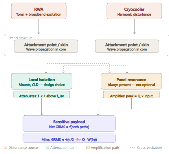
Reaction Wheel Assemblies (RWAs): The most prevalent source of jitter. Structural imperfections, alongside static and dynamic wheel imbalances, manifest as forces and moments proportional to the square of the wheel speed. Because RWA speeds constantly change to manage momentum, their discrete harmonics sweep across a broad frequency range—inevitably crossing and exciting local panel modes.
Cryocoolers: Stirling or pulse-tube cryocoolers used for cooling infrared detectors utilize reciprocating linear compressors. These typically operate at a fixed fundamental frequency (often between 40 Hz and 60 Hz). Though manufactured with active force-cancellation systems, their residual forces and higher-order harmonics can easily drive localized panel “breathing” modes.
Solar Array Drive Mechanisms (SADMs): Stepper motors driving solar tracking can cause micro-stepping transients. While low in continuous energy, these step inputs act as impulse functions that can cause lightly damped panel structures to ring out at their natural frequencies.
Payload Mechanism Actuators: Optical cryo-shutters, filter wheels, and fast-steering mirrors introduce localized, transient disturbances during operation.
Structural Mitigation for Jitter
To mitigate micro-vibrations, panel design requires a dual strategy: Frequency Separation and Isolation.
If a cryocooler operates at a fixed 50 Hz, the local panel bay must be designed via core or stiffener tailoring to ensure its modes sit well clear of 50 Hz and its primary harmonics (100 Hz, 150 Hz). Furthermore, placing high-jitter sources on localized isolation mounts (soft elastomer or spring-damper interfaces) attenuates high-frequency energy before it can inject itself into the broader panel structure.
Component Mounting Location
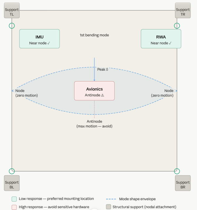
The spatial placement of components on a panel is just as important as the panel’s overall structural properties.
For a classic rectangular panel, the center of the panel is an antinode for the fundamental bending mode. This is the region of maximum modal displacement and acceleration. Conversely, edges, corners, support points, closeout frames, and stiffener intersections represent low-response nodal regions.
Rule of Thumb: Mount highly sensitive components—such as Inertial Measurement Units (IMUs), star trackers, reaction wheels, and delicate optical payloads—near panel supports, corners, or stiffener intersections. Avoid placing them at the center of an unsupported panel bay.
If a component must be placed in a high-displacement area due to volume constraints, local stiffening strategies should be deployed:
- Localized facesheet doublers.
- Intercostals or machined rib stiffeners.
- Local honeycomb core densification (foamed or potted cores).
- Wider component mounting plates to distribute the mechanical impedance.
Stiffener Layout and Acoustic Crossover
Orthogrid, isogrid, and rib-stiffened layouts can raise panel bending frequencies efficiently for a given areal density. Proper stiffener placement breaks up large flexible panel bays into smaller sub-panels with higher local frequencies.
However, there is a distinct crossover between structural random vibration control (base-driven) and acoustic response control (airborne cabin noise during launch). A rough practical boundary for this crossover sits around 500 Hz.
Below 500 Hz: Structural response is generally dominated by global panel modes excited by base-driven launch vehicle vibration. Raising the fundamental frequency helps lift the structure out of low-frequency high-energy input bands.
Above 500 Hz: Liftoff acoustic excitation takes over. Large panels act like acoustic speakers in reverse; the high surface-area-to-mass ratio allows acoustic pressure waves to couple directly into the skin bays. A panel that is highly rigid globally may still exhibit high-frequency, localized “skin-bay” breathing modes that severely punish small components mounted directly to the skin.
Material Selection Matrix
Material selection dictates the boundaries of your stiffness, mass, damping, and thermal performance.
| Material system | Specific stiffness |
Damping (Q) | Engineering tradeoffs |
|---|---|---|---|
|
Al 6061-T6 plate
Solid aluminum
|
Moderate | Q 30–50Low | Simple, cheap, isotropic, easy to machine. Mass-inefficient for primary large-area panels. |
|
Al honeycomb sandwich
Al facesheets + Al core
Industry baseline
|
Very high | Q 20–40Moderate | Excellent bending stiffness-to-mass ratio. Standard bus baseline. Susceptible to acoustic skin-bay modes. |
|
CFRP solid laminate
Carbon/epoxy layup
|
Very high | Q 40–60Low | Tailorable anisotropy, highly mass-efficient. Complex manufacturing and insert integration. |
|
CFRP facesheets / Al core
CFRP + honeycomb
High-performance standard
|
Extremely high | Q 30–50Low | Premium bus standard. Low CTE for thermal stability. Highly resonant — damping treatment often required. |
|
CFRP with CLD
Constrained layer damping
Micro-vib applications
|
High–very high | Q 8–15High | Best micro-vibration suppression for high-pointing-accuracy missions. Mass and outgassing qualification penalties apply. |
Quick Sizing Workflow
When kicked off on a preliminary sizing exercise, follow this structured loop:
1. Analyze the Input PSD Shape: Do not assume all random curves are flat. Note where the ramps, plateaus, and roll-offs sit.
2. Determine Component Allowables: Identify the qualification/acceptance $G_{\text{RMS}}$ limit of your target component.
3. Calculate Allowable $f_n Q$ via Miles’ Equation: Rearrange Miles’ equation to find your boundary target:
$$f_n Q \approx \frac{\ddot{x}_{\text{rms}}^2}{\frac{\pi}{2} W(f_n)}$$
4. Iterate Geometry for Frequency Placement: Adjust core thickness, span lengths, and boundary conditions to land $f_n$ in a favorable valley of the launch PSD or well away from on-orbit operational frequencies.
5. Apply Targeted Damping: If frequency placement is constrained by volume and $Q$ remains too high, integrate viscoelastics at high-strain regions (modal strain energy centers, typically near boundaries/stiffener interfaces).
6. Verify with FEA: Run a random vibration analysis using a fine-meshed Finite Element Model. Ensure your modal truncation mass fraction reaches at least 90% to catch localized skin modes.
7. Correlate via Test: Run a low-level sine sweep or tap test on physical development units to extract actual $f_n$ and $Q$ values. Update your analytical damping assumptions accordingly.
Final Thought
Strength design gives you a survivable structure; frequency and damping design give you an operational environment.
For high-performance satellite bus panels, minimizing $G_{\text{RMS}}$ and jitter is achieved not by chasing maximum stiffness alone, but by balancing frequency placement relative to environmental spectra, mitigating transmission through localized isolation, and leveraging damping where resonances inevitably occur.
See also: Spacecraft On-orbit Vibration
Tom Irvine