VibrationData Blog | Structural Materials
If you have ever looked at a stress-strain curve for mild (low-carbon) steel and wondered why it has that distinctive “flat shelf” between the upper and lower yield points, you are not alone. That plateau is one of the most visually distinctive features in all of materials science—and the physics behind it is worth understanding, especially for engineers who rely on steel’s ductility for energy absorption, seismic design, impact resistance, and failure prediction.
The stress-strain curve of mild steel is more than just a material property chart. It is a direct macroscopic manifestation of the underlying motion of dislocations through a crystalline lattice. It provides a rare opportunity to observe microscopic metallurgical processes through a simple, macroscopic laboratory tensile test.
A Note on Universality: The classic upper-yield and lower-yield behavior is primarily associated with annealed or normalized low-carbon ferritic steels. Many structural steels exhibit only a mild yield plateau, while quenched-and-tempered steels, stainless steels, aluminum alloys, and many modern high-strength alloys transition smoothly from elastic to plastic deformation. In those materials, yield strength must be defined using an empirical $0.2\%$ offset criterion ($0.002$ plastic strain) rather than an observed yield plateau.
1. The Elastic Region: Everything Is Reversible
Load a steel coupon slowly in a tensile test machine, and it behaves like a very stiff spring. Stress and strain increase together in a linear relationship described by Hooke’s Law:
$$\sigma = E \cdot \varepsilon$$
Where:
- $\sigma$ is the engineering stress
- $\varepsilon$ is the engineering strain
- $E$ is Young’s modulus (approximately $200\text{ GPa}$ for structural steel)
Remove the load anywhere within this region, and the specimen returns precisely to its original dimensions. No permanent deformation occurs. At the atomic level, iron-to-iron metallic bonds stretch elastically while dislocations remain essentially stationary. The stored strain energy is fully recoverable, which is why structures operating entirely within the elastic regime return to their original shape after unloading.
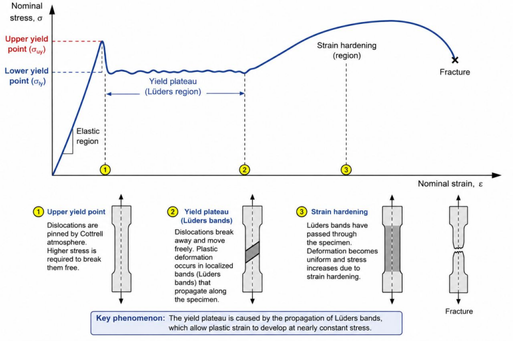
2. The Upper Yield Point: Dislocations Pinned by Solute Atoms
At the peak of the elastic curve sits the upper yield point, $\sigma_{uy}$. This is not simply where plastic deformation begins in a generic sense. Instead, it reflects a specific metallurgical phenomenon involving dislocation pinning by interstitial solute atoms.
In low-carbon steel, interstitial carbon and nitrogen atoms diffuse over time toward the distorted, high-strain fields surrounding edge dislocations. Because these solute atoms distort the lattice, they find a lower energy state by nesting in the expanded region beneath an extra half-plane of iron atoms. This forms what materials scientists call Cottrell atmospheres—localized clouds of solute atoms that effectively anchor or “pin” dislocations in place.
To initiate plastic deformation, the applied shear stress must rise high enough to violently tear the dislocations free from these pinning atmospheres. Consequently, the measured stress rises to a transient peak ($\sigma_{uy}$) that significantly exceeds the stress actually required to sustain continued plastic flow once the dislocations are mobile.
The upper yield point is primarily a consequence of dislocation pinning rather than an intrinsic measure of the material’s bulk plastic-flow resistance.
Because carbon and nitrogen atoms slowly migrate back toward dislocations at room temperature, an effect known as strain aging occurs. If a steel specimen is plastically deformed, unpinned, and then allowed to rest (or baked at a low temperature), the solute atoms will re-diffuse to the new dislocation cores. Upon retesting, the pronounced upper yield point returns, often accompanied by an increase in strength and a distinct loss of ductility.
3. The Drop to the Lower Yield Point: Dislocations Break Free
Once the initial population of dislocations breaks free from its Cottrell atmospheres, a cascade effect occurs. The unpinned dislocations multiply rapidly via Frank-Read sources and can now move through the crystal lattice at a much lower energy threshold.
As a result, the stress required to sustain deformation drops abruptly to the lower yield point, $\sigma_{ly}$.
During a tensile test, the measured load often drops sharply and oscillates lightly as new dislocation sources activate across different grains. Because the upper yield point is highly sensitive to testing variables—such as machine alignment, specimen surface roughness, temperature, and strain rate (higher strain rates artificially elevate $\sigma_{uy}$)—it is fundamentally unreliable for structural engineering calculations.
Engineering Standard: Structural design specifications (such as AISC or ASTM standards) universally rely on the lower yield strength ($\sigma_{ly}$) or a specified minimum yield strength ($F_y$) rather than the volatile upper yield point.
4. The Yield Plateau: Lüders Bands Propagate
The flat, oscillating region following the drop is known as the yield plateau or Lüders region, named after the German engineer Wilhelm Lüders, who documented the phenomenon in 1860.
During this stage, plastic deformation does not occur uniformly throughout the specimen. Instead, it localizes into highly visible, discrete shear bands called Lüders bands (or stretcher-strain markings).
A Lüders band typically nucleates at a structural discontinuity, surface imperfection, or near the specimen grips where stress concentrations are highest. It then propagates along the gauge length at an angle of approximately $45^\circ$ to the tensile loading axis. This specific orientation corresponds to the planes of maximum resolved shear stress ($\tau_{max}$) under uniaxial tension, as predicted by Mohr’s Circle. Because dislocation glide is driven purely by shear stress, plastic slip naturally follows these preferred directions.
During the propagation of a Lüders band:
- Material behind the advancing band front has already yielded and is deforming plastically.
- Material ahead of the band front remains entirely elastic.
- The band front itself advances down the specimen at a nearly constant stress level ($\sigma_{ly}$).
Macroscopically, while the testing machine continually pulls the specimen, the load cells register a flat shelf because the extension is being entirely accommodated by the propagation of the Lüders front rather than uniform stretching.
The total strain accumulated during this plateau is called the Lüders strain or yield-point elongation (YPE), and typically spans $1\%$ to $3\%$ strain for mild steels.
5. Strain Hardening: Uniform Plastic Flow Returns
Once the Lüders bands have completely swept across the entire gauge length, every grain within the material has finally yielded. With the mobile dislocations now free from their original Cottrell atmospheres, uniform plastic deformation returns, and the material enters the strain hardening (or work hardening) regime.
Further plastic deformation now requires a continuous increase in applied stress. This occurs because:
- Dislocation density increases exponentially ($\rho \approx 10^{10}\text{ cm}^{-2}$ to $10^{12}\text{ cm}^{-2}$).
- Dislocations begin intersecting, tangling, and forming immobile networks (dislocation forests).
- Grain boundaries act as geometric barriers to slip (Hall-Petch effect), causing dislocations to pile up and create internal back-stresses.
This strain-hardening regime is commonly modeled mathematically using Hollomon’s equation for true stress ($\sigma_{true}$) and true plastic strain ($\varepsilon_{true}$):
$$\sigma_{true} = K \cdot (\varepsilon_{true})^n$$
Where:
- $K$ is the material’s strength coefficient.
- $n$ is the strain-hardening exponent.
For most mild structural steels, $n$ ranges between $0.15$ and $0.25$. A high $n$-value is vital in metal-forming operations because it dictates how well a material can distribute strain; a highly strain-hardening material resists localized thinning by strengthening areas that deform first.
The stress curve rises smoothly until it hits the Ultimate Tensile Strength (UTS). At this peak, geometric softening (the reduction of the specimen’s cross-sectional area) begins to outpace the microstructural strengthening of strain hardening. This instigates localized necking.
Beyond this point, engineering stress drops because it is calculated using the original cross-sectional area ($A_0$). However, the true stress (calculated using the actual instantaneous area, $A$) continues to climb right up until failure.
$$\sigma_{engineering} = \frac{P}{A_0} \quad \text{vs.} \quad \sigma_{true} = \frac{P}{A}$$
6. Ductile Fracture
Eventually, the localized strain within the neck becomes unsustainable, and the specimen fractures. For ductile, low-carbon steels, failure occurs via microvoid coalescence:
- Void Nucleation: Microscopic voids form at localized stress concentrations, typically at interfaces between the ferrite matrix and rigid cementite ($\text{Fe}_3\text{C}$) particles or manganese sulfide ($\text{MnS}$) inclusions.
- Void Growth: Voids expand along shear planes under continued triaxial tensile stress.
- Coalescence: Neighboring voids merge, forming an internal, macroscopic crack.
- Final Rupture: The crack propagates outward, culminating in a $45^\circ$ shear lip that creates the classic cup-and-cone fracture surface.
While total elongation at fracture measures basic ductility, toughness represents the total material capacity to absorb energy per unit volume before breaking. It is mathematically equivalent to the total integrated area under the stress-strain curve from zero load to fracture:
$$\text{Toughness} = \int_{0}^{\varepsilon_f} \sigma \cdot d\varepsilon$$
Summary of Engineering Implications
The table below outlines how these microstructural phenomena dictate the practical constraints faced by civil, manufacturing, and metallurgical engineers.
| Phenomenon | Metallurgical Origin | Engineering & Design Relevance |
| Upper Yield Point ($\sigma_{uy}$) | Dislocation breakout from Cottrell atmospheres | Unreliable for design; causes unpredictable “burst-type” initial yielding. |
| Lower Yield Point ($\sigma_{ly}$) | Steady-state motion of unpinned dislocations | The baseline for $F_y$ in AISC/ASTM structural design codes. |
| Lüders Plateau / YPE | Localized propagation of Lüders shear bands | Causes unsightly stretcher-strain lines on stamped auto body panels. |
| Strain-Hardening ($n$) | Dislocation entanglement and density increase | Key indicator for sheet-metal formability and resistance to localized necking. |
| Strain Aging | Interstitial atoms re-pinning dislocations over time | Increases yield strength but dangerously reduces ductility and toughness. |
| Area Under the Curve | Total plastic work capacity | Measures toughness; vital for surviving seismic events or explosive blasts. |
The Industrial Reality: Managing the Yield Point
In Manufacturing (Sheet Metal Stamping)
The Lüders plateau is an absolute nuisance for automotive and appliance manufacturers. When sheet steel is stamped into a car door or refrigerator panel, the localized Lüders bands leave permanent, visible ridges on the surface known as fluting or stretcher strains. To prevent this, steel mills pass finished steel coils through a light skin-pass (temper rolling) operation. This process applies a minuscule cold-work reduction (typically less than $1\%$). It introduces just enough mobile dislocations across the entire sheet to completely eliminate the yield-point elongation without drastically altering the steel’s core ductility.
In Structural and Seismic Engineering
In Structural and Seismic Engineering
Conversely, structural engineers view the yield plateau as an extraordinary asset. During a major seismic or blast event, a building’s steel frames are designed to undergo controlled inelastic deformation — plastic hinging — to dissipate the massive kinetic energy of the event. Because mild steel features a broad yield plateau, structural components can experience significant plastic rotation and displacement while maintaining a constant load-bearing capacity without generating higher force demands on adjacent columns or foundations. The stable combination of a clear yield plateau, high ductility, and steady strain hardening makes low-carbon structural steel one of the most resilient energy-absorbing materials ever discovered.
This behavior has direct and codified consequences for the structural steel beams specified in ASCE 7-22 seismic designs. Under ASCE 7-22, buildings in moderate-to-high seismic zones are designed using a seismic response modification coefficient R greater than unity, which explicitly assumes that the structural system will undergo controlled inelastic deformation before collapse. The beams in Special Moment Frames (SMF) and Intermediate Moment Frames (IMF) are required by AISC 341 to be fabricated from steels with a well-defined yield plateau, typically ASTM A992 wide-flange sections. A992 steel carries a maximum yield-to-tensile ratio of 0.85 and a minimum elongation requirement, both of which ensure that the strain-hardening reserve and the stable yield plateau are present and reliable.
During a design-level seismic event, plastic hinges form at beam ends within designated protected zones, and it is precisely the broad Lüders plateau — the ability to sustain large plastic rotations at a nearly constant moment — that allows those hinges to dissipate seismic energy without shedding load onto columns or connections. ASCE 7-22 Table 12.2-1 assigns the highest R values only to systems where this ductile hinging behavior is guaranteed by both material specification and detailing requirements. Strain aging is also a practical concern in this context: field welding operations that locally heat and then slowly cool beam sections near connections can re-pin dislocations, raise the effective yield strength above the nominal F_y, and reduce the rotational ductility that the seismic design depends upon — a phenomenon addressed by AISC 341 through limitations on weld heat input and requirements for notch-tough filler metals in demand-critical welds.
Modern Advanced High-Strength Steels (AHSS)
It is worth noting that the textbook upper-and-lower yield point behavior is increasingly absent in modern high-performance materials. Advanced High-Strength Steels (AHSS), Dual-Phase (DP) steels, and TRIP (Transformation-Induced Plasticity) steels are deliberately engineered to suppress the yield plateau.
By utilizing complex, multi-phase microstructures (such as hard martensite islands embedded within a soft ferrite matrix), these modern alloys feature a high density of unpinned mobile dislocations from the moment they are manufactured. They yield smoothly and continuously, offering vastly superior strength-to-weight ratios and exceptional formability without surface defects.
While the classic Lüders plateau remains one of metallurgy’s most elegant examples of dislocation-controlled plasticity, it stands today as a unique signature of traditional mild steel—a material whose atomic-scale physics perfectly aligns with the safety demands of modern infrastructure.
– Tom Irvine
📌 Related Earthquake Engineering Knowledge Hub
This article is featured in our main Earthquake Engineering & Structural Dynamics Hub . Visit the hub to explore related articles on shock response spectra, time history analysis, seismic equipment qualification, and structural case studies.