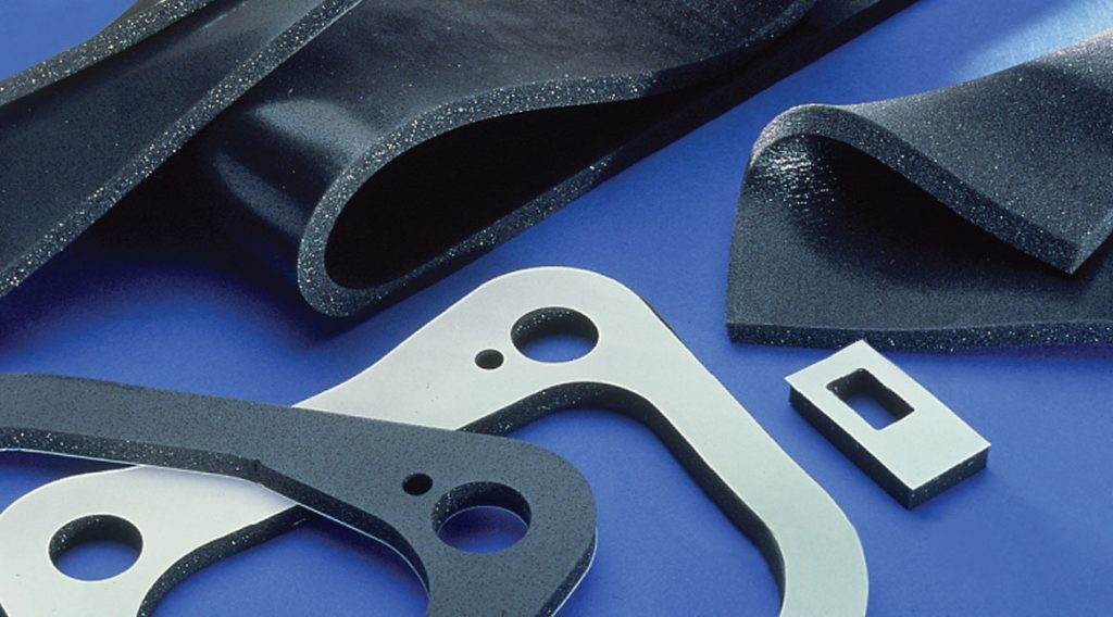
PORON® is a commercial polyurethane foam, Rogers Corporation
Introduction
Microcellular Urethane (MCU) mounts are a highly capable candidate for this application and are widely utilized for military electronics isolation. Several aerospace and defense manufacturers offer products with extensive MIL-STD-810 qualification data and field history in tactical vehicle environments.
However, success depends on moving past simple static catalog data. Proper mount selection requires a rigorous evaluation of dynamic stiffness overrides, shock travel margins, temperature-induced glass transitions, and long-term hysteretic thermal buildup during random vibration testing.
Why MCU Works Well in Severe Environments
MCU behaves as a highly nonlinear, viscoelastic, open-cell foam isolator. Under low-amplitude, operational random vibration levels, it operates in a relatively compliant regime, providing excellent high-frequency vibration isolation. Under high-amplitude shock loading, the cellular matrix collapses and the material progressively stiffens. This non-linear behavior limits excessive displacement and prevents the severe structural damage associated with hard mechanical bottoming out.
This dual-regime characteristic is ideal for systems that must concurrently survive:
- MIL-STD-810H, Method 514.8: Annex D, Category 4 (Composite Wheeled Vehicle) random vibration profiles.
- MIL-STD-810H, Method 516.8: Functional and crash-hazard shock pulses.
Key Advantages
- High Inherent Damping: Loss factors ($\eta$) typically range from $0.2$ to $0.4$, significantly reducing resonant amplification compared to steel springs or low-damping elastomers.
- Progressive Stiffening: Eliminates metal-on-metal impacts during extreme shock events through a graceful, non-linear force-deflection curve.
- Fatigue & Environmental Resistance: Superior resistance to oil, ozone, and structural tearing compared to liquid silicone gel-type isolators.
- Compact Packaging: High energy density absorption per unit volume allows for low-profile clearance profiles.
Dynamic Versus Static Stiffness
One of the most common pitfalls in isolation design is estimating the system’s natural frequency directly from a static load-deflection curve. Viscoelastic materials exhibit structural properties that vary drastically based on:
- Frequency of excitation
- Dynamic strain amplitude
- Static preload (mean strain)
- Ambient operating temperature
In practice, the dynamic stiffness ($k_{\text{dyn}}$) is significantly higher than the static stiffness ($k_{\text{stat}}$). For typical MCU formulations, the dynamic stiffness override factor ranges from:
$$\frac{k_{\text{dyn}}}{k_{\text{stat}}} \approx 1.5 \text{ to } 3.0$$
As a result, an isolation system predicted to provide a $15\text{ Hz}$ natural frequency using static catalog data will actually shift higher in service—often behaving closer to $22\text{ Hz}$ to $26\text{ Hz}$. This shift pushes the resonant frequency directly into bands containing higher environmental energy, potentially destroying its isolation capabilities.
Engineering Action Item: Always request measured Storage Modulus ($E’$), Loss Modulus ($E”$), and Dynamic Stiffness versus Frequency/Preload curves rather than relying on static load-deflection metrics.
Transmissibility Design Check
For a base-excited, single-degree-of-freedom (SDOF) system, the displacement and acceleration transmissibility ($T_r$) is modeled by the classic uncoupled equation:
$$T_r = \sqrt{\frac{1 + (2\zeta r)^2}{(1 – r^2)^2 + (2\zeta r)^2}}$$
where the frequency ratio $r$ is defined as:
$$r = \frac{f}{f_n}$$
and:
- $f$ = excitation frequency ($\text{Hz}$)
- $f_n$ = system dynamic natural frequency ($\text{Hz}$)
- $\zeta$ = critical damping ratio ($\zeta = \frac{\eta}{2}$)
For any isolation system, attenuation (transmissibility falling below unity, or $T_r < 1$) only occurs when the frequency ratio satisfies:
$$r > \sqrt{2}$$
While a lightly damped steel spring isolator might exhibit a resonant amplification factor ($Q$) exceeding $10$ at $r=1$, the high damping ratio ($\zeta \approx 0.10 \text{ to } 0.20$) of MCU restricts the resonant peak to a manageable $Q \approx 2.5 \text{ to } 5.0$.
For military electronics mounted on vehicle bulkheads, dynamic natural frequencies in the range of 15 to 25 Hz are typically targeted to achieve a balance between vibration isolation and allowable shock travel clearance.
Shock Requirements — 40 g, 11 ms Terminal-Peak Sawtooth
The terminal-peak sawtooth pulse specified in MIL-STD-810H Method 516.8 is asymmetric and rich in high-frequency residual energy. However, when designing a relatively low-frequency isolation system ($15 \text{ to } 25\text{ Hz}$), the primary challenge is rarely the raw acceleration transmission; it is managing the enclosure’s relative displacement clearance (rattle space).
To evaluate this space, we can estimate the maximum relative dynamic displacement ($x_{\max}$) experienced by the isolated component during a sudden base transient. For a low-frequency system subjected to a pulse where the shock duration is significantly shorter than the natural period of the mount, the peak relative displacement can be approximated via the shock acceleration input:
$$x_{\max} \approx \frac{a}{\omega_n^2}$$
where:
- $a$ = peak input acceleration ($\text{m/s}^2$ or $\text{in/s}^2$)
- $\omega_n = 2\pi f_n$ = angular natural frequency ($\text{rad/s}$)
Let’s look at how this impacts a system with a target dynamic natural frequency of $f_n = 15\text{ Hz}$ ($\omega_n \approx 94.25\text{ rad/s}$) under the specified $40\text{g}$ pulse. Converting the input to standard units ($a = 40 \times 9.81 \text{ m/s}^2 = 392.4 \text{ m/s}^2$), the required clearance is:
$$x_{\max} \approx \frac{392.4}{(94.25)^2} \approx 0.0442\text{ m} \approx 44.2\text{ mm } (1.74\text{ inches})$$
This calculation reveals that available rattle space—not static load capacity—is the governing design constraint. If your vehicle enclosure or mounting rack cannot accommodate nearly $1.75\text{ inches}$ of structural deflection during a crash or high-impact event, you will be forced to select a stiffer mount. Shifting $f_n$ upward will reduce the required travel distance, but you must accept higher raw vibration transmission during normal operation as a trade-off.
Shock Response Spectrum (SRS) Considerations
For critical internal components (circuit cards, crystal oscillators, and connectors), evaluating the peak acceleration of the raw pulse is insufficient. The Shock Response Spectrum (SRS) must be analyzed.
The specified $40\text{g}, 11\text{ ms}$ sawtooth pulse represents the input base environment. A properly tuned MCU isolation system acts as a mechanical low-pass filter, transforming that high-frequency input into a drastically smoothed, lower-acceleration response SRS curve for the internal components.
Whenever executing selection simulations, compare the SRS of the isolated mass against the component-level fragility thresholds of your internal PCBAs.
Random Vibration — The Ultimate Durability Challenge
While shock events grab attention, the MIL-STD-810 Method 514.8 Composite Wheeled Vehicle random vibration profile is the true destroyer of hardware via high-cycle fatigue and thermal breakdown.
Because MCU is highly viscoelastic, it dissipates kinetic energy by converting it into heat via internal molecular hysteresis. For a long-duration mission profile, this internal damping results in localized heat generation inside the core of the elastomer. If the heat generation rate exceeds the thermal dissipation rate of the mounting boundary conditions, the core temperature can spike, leading to:
- Thermal softening (dropping the natural frequency into dangerous structural resonance bands)
- Accelerated compression set (permanent plastic deformation and loss of preload)
- Accelerated material aging and cracking
Ensure your supplier provides qualification data confirming property retention under long-duration random vibration exposure at full payload mass.
Temperature Sensitivity
Temperature extremes pose a significant risk to polyurethane materials. MCU undergoes severe modulus shifts across the standard MIL-STD-810 operational envelope:
- At Low Operational Temperature ($-46^\circ\text{C}$): The material approaches its glass transition region ($T_g$). The storage modulus spikes violently, turning the compliant isolator into a rigid, highly conductive block that transmits high-frequency vibration straight to the electronics.
- At High Operational Temperature ($+71^\circ\text{C}$): The polymer chains relax. The material softens, lowering the natural frequency and significantly increasing the risk of structural bottoming out during shock events.
Ensure that the isolation system’s resonant frequency remains within safe functional boundaries at both extreme thermal limits.
Structural Integration & Vehicle Amplification
A common system integration error is treating the vehicle floor as a completely rigid foundation that matches the raw MIL-STD-810 Power Spectral Density (PSD) specification.
In reality, vehicle structures are highly flexible. Equipment racks, mounting rails, bulkheads, and adapter plates possess local resonances that can amplify the vehicle floor’s vibration input by factors of $2\times$ to $5\times$ before it ever reaches the base of the MCU isolator.
Always evaluate candidate isolators using the localized, amplified PSD expected at the exact mounting interface point rather than generic, vehicle-level global specifications.
Material Comparison: Gel vs. MCU
| Property / Metric | Gel-Type Isolators | Microcellular Urethane (MCU) |
| Shock Attenuation | Excellent (Very compliant initial travel) | Excellent (Progressive energy absorption) |
| Random Vibration Attenuation | Good | Good |
| Mechanical Durability | Poor to Moderate (Prone to tearing under shear) | Good (High tensile and tear strength) |
| Fatigue Life | Moderate | Excellent |
| Thermal Sensitivity | High Shift | Moderate Shift |
| Long-Term Creep / Compression Set | Moderate to High | Excellent Resistance |
| Cost Matrix | High | Low to Moderate |
| Military Qualification History | Limited Specialty Cases | Extensive Field Deployment |
Verified Industry Suppliers (Defense Track Record)
Recommended Next Steps for Procurement
When contacting application engineers, prepare a unified technical interface data sheet. Providing the following baseline parameters will ensure rapid, precise sizing simulations:
- Total Supported Mass & Mass Properties: Precision weight, center-of-gravity (CG) location vector, and mass moments of inertia ($I_{xx}, I_{yy}, I_{zz}$).
- Mounting Orientation Layout: Footprint dimensions and geometry (e.g., base-mounted, symmetric center-of-gravity plane mounting, or wall-mounted).
- Shock Specification Input: Complete definition of the $40\text{g}, 11\text{ ms}$ terminal-peak sawtooth profile, including number of shocks required per orthogonal axis.
- Vibration Profile Input: The exact input Breakpoint Table PSD ($\text{g}^2/\text{Hz}$ vs. Frequency) from MIL-STD-810H Method 514.8.
- Physical Space Envelopes: Absolute maximum allowable rattle space clearance in all three dimensions to bound shock travel limits.
- Thermal Boundaries: Extreme storage and operational temperature ranges (e.g., $-46^\circ\text{C}$ to $+71^\circ\text{C}$).
Conclusion
In heavy combat and tactical wheeled vehicle environments, the design driver is rarely surviving the peak acceleration of the shock pulse itself. The real engineering art lies in maintaining a sufficiently low dynamic natural frequency to isolate random vibration, while simultaneously controlling transient rattle space displacement and accounting for environmental temperature variations.
MCU mounts offer an optimized compromise of high damping, non-linear progressive load protection, high-cycle durability, and proven military field history. Final validation must always verify the design across the full dynamic, thermal, and structural boundaries of the vehicle integration platform.
Tom Irvine